

Software Guide
Page 4
Contents 2 C H A P T E R Getting Started with CMS 2-1 Features 2-2 Front Panel View 2-4 Cluster Tree 2-5 Front-Panel Images 2-6 Redundant Power System LED 2-7 Port Modes and LEDs 2-8 VLAN Membership Modes 2-12 Topology View 2-13 Topology Icons 2-15 Device and Link Labels 2-16 Colors in ... List 2-30 Tabs, Lists, and Tables 2-31 Icons Used in Windows 2-31 Buttons 2-31 Accessing CMS 2-32 Access Modes in CMS 2-33 Catalyst 2900 Series XL and Catalyst 3500 Series XL Software Configuration Guide iv 78-6511-08
Contents 2 C H A P T E R Getting Started with CMS 2-1 Features 2-2 Front Panel View 2-4 Cluster Tree 2-5 Front-Panel Images 2-6 Redundant Power System LED 2-7 Port Modes and LEDs 2-8 VLAN Membership Modes 2-12 Topology View 2-13 Topology Icons 2-15 Device and Link Labels 2-16 Colors in ... List 2-30 Tabs, Lists, and Tables 2-31 Icons Used in Windows 2-31 Buttons 2-31 Accessing CMS 2-32 Access Modes in CMS 2-33 Catalyst 2900 Series XL and Catalyst 3500 Series XL Software Configuration Guide iv 78-6511-08

Software Guide
Page 28
... station that is a graphical user interface that can configure and monitor the switch-on the switch. Catalyst 2900 Series XL and Catalyst 3500 Series XL Software Configuration Guide 1-6 78-6511-08 CMS is enhanced to the switch console port or by using these topics: ...Management Platforms" section on page 1-7 Management Interface Options You can also display network topologies to gather link information and to display switch images to the other devices in your management station directly to support desktop-switching features. You can fully configure and monitor a standalone ...
... station that is a graphical user interface that can configure and monitor the switch-on the switch. Catalyst 2900 Series XL and Catalyst 3500 Series XL Software Configuration Guide 1-6 78-6511-08 CMS is enhanced to the switch console port or by using these topics: ...Management Platforms" section on page 1-7 Management Interface Options You can also display network topologies to gather link information and to display switch images to the other devices in your management station directly to support desktop-switching features. You can fully configure and monitor a standalone ...

Software Guide
Page 29
... switches from the LEDs on the front-panel images. The system, redundant power system (RPS), and port LED colors on the images are some examples of Using CMS and Clustering ... status of their geographic proximity and interconnection media, including Ethernet, Fast Ethernet, Fast EtherChannel, Cisco GigaStack Gigabit Interface Converter (GBIC), Gigabit Ethernet, and Gigabit EtherChannel connections. NTP, STP, ...Switches." 78-6511-08 Catalyst 2900 Series XL and Catalyst 3500 Series XL Software Configuration Guide 1-7 For more information about switch clusters, see Chapter 2, "Getting...
... switches from the LEDs on the front-panel images. The system, redundant power system (RPS), and port LED colors on the images are some examples of Using CMS and Clustering ... status of their geographic proximity and interconnection media, including Ethernet, Fast Ethernet, Fast EtherChannel, Cisco GigaStack Gigabit Interface Converter (GBIC), Gigabit Ethernet, and Gigabit EtherChannel connections. NTP, STP, ...Switches." 78-6511-08 Catalyst 2900 Series XL and Catalyst 3500 Series XL Software Configuration Guide 1-7 For more information about switch clusters, see Chapter 2, "Getting...

Software Guide
Page 46
...complex features - The candidate, member, and link popup menus provide options for performing tasks from the window Catalyst 2900 Series XL and Catalyst 3500 Series XL Software Configuration Guide 2-2 78-6511-08 The Topology view displays a network map that uses icons that represent switch clusters, cluster... this view, you can be displayed at the same time: - The Front Panel view displays the front-panel image of a specific switch or the front-panel images of all switches in the cluster. Device Manager is launched from a command switch, the Front Panel view displays the...
...complex features - The candidate, member, and link popup menus provide options for performing tasks from the window Catalyst 2900 Series XL and Catalyst 3500 Series XL Software Configuration Guide 2-2 78-6511-08 The Topology view displays a network map that uses icons that represent switch clusters, cluster... this view, you can be displayed at the same time: - The Front Panel view displays the front-panel image of a specific switch or the front-panel images of all switches in the cluster. Device Manager is launched from a command switch, the Front Panel view displays the...

Software Guide
Page 48
... 3500XL-12 3500XL-12 Right-click the command switch image to view or change system-related settings. related option. Catalyst 2900 Series XL and Catalyst 3500 Series XL Software Configuration Guide 2-4 78-6511-08 65720 Right-click a member switch image to display the device pop-up menu, and select... 65718 Cluster tree. port or link status. Figure 2-2 Front Panel View from a command switch, the Front Panel view displays the front-panel images of the switch and connected RPS. Right-click a port to Press Ctrl, and then display the port pop-up menu, and select a ...
... 3500XL-12 3500XL-12 Right-click the command switch image to view or change system-related settings. related option. Catalyst 2900 Series XL and Catalyst 3500 Series XL Software Configuration Guide 2-4 78-6511-08 65720 Right-click a member switch image to display the device pop-up menu, and select... 65718 Cluster tree. port or link status. Figure 2-2 Front Panel View from a command switch, the Front Panel view displays the front-panel images of the switch and connected RPS. Right-click a port to Press Ctrl, and then display the port pop-up menu, and select a ...

Software Guide
Page 49
... scroll down the window to communicate with the member switch. 78-6511-08 Catalyst 2900 Series XL and Catalyst 3500 Series XL Software Configuration Guide 2-5 The colors of the devices in the left -click the icon or image. The internal fan of its members. Chapter 2 Getting Started with a yellow outline. • To select...
... scroll down the window to communicate with the member switch. 78-6511-08 Catalyst 2900 Series XL and Catalyst 3500 Series XL Software Configuration Guide 2-5 The colors of the devices in the left -click the icon or image. The internal fan of its members. Chapter 2 Getting Started with a yellow outline. • To select...

Software Guide
Page 50
...For more information about the read -only. The port is read -only access mode, see the "Port Modes and LEDs" section on the front-panel image. Figure 2-5 Port Icons Table 2-2 describes the colors representing the wavelengths on page 2-33. For port status LED information, see the "Access Modes in CMS... 1530 nm 1550 nm 1570 nm 1590 nm 1610 nm Color Gray Violet Blue Green Yellow Orange Red Brown Catalyst 2900 Series XL and Catalyst 3500 Series XL Software Configuration Guide 2-6 78-6511-08 This section includes descriptions of ports that you want to select, and then release the...
...For more information about the read -only. The port is read -only access mode, see the "Port Modes and LEDs" section on the front-panel image. Figure 2-5 Port Icons Table 2-2 describes the colors representing the wavelengths on page 2-33. For port status LED information, see the "Access Modes in CMS... 1530 nm 1550 nm 1570 nm 1590 nm 1610 nm Color Gray Violet Blue Green Yellow Orange Red Brown Catalyst 2900 Series XL and Catalyst 3500 Series XL Software Configuration Guide 2-6 78-6511-08 This section includes descriptions of ports that you want to select, and then release the...

Software Guide
Page 52
... Port Modes Mode LED Description STAT Ethernet link status of information displayed through the port LEDs. Default mode on the Catalyst 3524-PWR XL 10/100 ports. Front Panel View Chapter 2 Getting Started with CMS Port Modes and LEDs The port modes (Table 2-6) determine the ...switch ports, or the Ethernet link status on the front-panel images. LINE PWR Inline power setting on these switches only. Default setting is auto. (Catalyst 3524-PWR XL only) Catalyst 2900 Series XL and Catalyst 3500 Series XL Software Configuration Guide 2-8 78-6511-08 Select Reports > Bandwidth ...
... Port Modes Mode LED Description STAT Ethernet link status of information displayed through the port LEDs. Default mode on the Catalyst 3524-PWR XL 10/100 ports. Front Panel View Chapter 2 Getting Started with CMS Port Modes and LEDs The port modes (Table 2-6) determine the ...switch ports, or the Ethernet link status on the front-panel images. LINE PWR Inline power setting on these switches only. Default setting is auto. (Catalyst 3524-PWR XL only) Catalyst 2900 Series XL and Catalyst 3500 Series XL Software Configuration Guide 2-8 78-6511-08 Select Reports > Bandwidth ...
Software Guide
Page 68
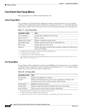
... display the device popup menu, click the switch icon from the command switch. 3. To display the port popup menu, click a specific port image, and right-click. Display a graph showing the bandwidth used port configuration windows from this menu option are available in use. Bandwidth Graphs Host ...port LED is green when in port status mode). 2-24 Catalyst 2900 Series XL and Catalyst 3500 Series XL Software Configuration Guide 78-6511-08 Available only from the cluster tree or the front-panel image itself, and right-click. Table 2-17 Device Popup Menu Popup Menu Option ...
... display the device popup menu, click the switch icon from the command switch. 3. To display the port popup menu, click a specific port image, and right-click. Display a graph showing the bandwidth used port configuration windows from this menu option are available in use. Bandwidth Graphs Host ...port LED is green when in port status mode). 2-24 Catalyst 2900 Series XL and Catalyst 3500 Series XL Software Configuration Guide 78-6511-08 Available only from the cluster tree or the front-panel image itself, and right-click. Table 2-17 Device Popup Menu Popup Menu Option ...

Software Guide
Page 78
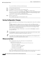
... save all configuration changes to Flash memory, they occur. 2-34 Catalyst 2900 Series XL and Catalyst 3500 Series XL Software Configuration Guide 78-6511-08 The configuration is an error in the window status bar. The front-panel images and CMS windows always display the running configuration. The change does not automatically become...
... save all configuration changes to Flash memory, they occur. 2-34 Catalyst 2900 Series XL and Catalyst 3500 Series XL Software Configuration Guide 78-6511-08 The configuration is an error in the window status bar. The front-panel images and CMS windows always display the running configuration. The change does not automatically become...
Software Guide
Page 88
...about and CLI procedures for the software features supported in privileged EXEC mode. Saving Configuration Changes The switch Flash memory stores the IOS image, the startup configuration file (config.txt file), and helper files. Note The write memory command does not apply to the Catalyst ... Catalyst 3500 Series XL Software Configuration Guide 3-8 78-6511-08 When you make sure you must enter the write memory command in this guide provides information about the Cisco Systems Access page, see the "Accessing CMS" section on Cisco.com (http://www.cisco.com/univercd/cc/td/doc/product...
...about and CLI procedures for the software features supported in privileged EXEC mode. Saving Configuration Changes The switch Flash memory stores the IOS image, the startup configuration file (config.txt file), and helper files. Note The write memory command does not apply to the Catalyst ... Catalyst 3500 Series XL Software Configuration Guide 3-8 78-6511-08 When you make sure you must enter the write memory command in this guide provides information about the Cisco Systems Access page, see the "Accessing CMS" section on Cisco.com (http://www.cisco.com/univercd/cc/td/doc/product...
Software Guide
Page 90
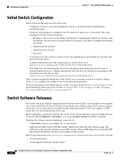
... the setup program is running. After you have assigned IP information to the switch, you can do not share the same software image. You can run the switch on Cisco.com and are in a switch cluster, the setup program also prompts for the name and password of the software that you plan..., or by using the show version user EXEC command. You also need a switch IP address if you might want to upgrade your Catalyst 2900 XL or Catalyst 3500 XL switch with the local routers and the Internet. For more information about IP information, see the "Accessing CMS" section on page 2-32 and...
... the setup program is running. After you have assigned IP information to the switch, you can do not share the same software image. You can run the switch on Cisco.com and are in a switch cluster, the setup program also prompts for the name and password of the software that you plan..., or by using the show version user EXEC command. You also need a switch IP address if you might want to upgrade your Catalyst 2900 XL or Catalyst 3500 XL switch with the local routers and the Internet. For more information about IP information, see the "Accessing CMS" section on page 2-32 and...

Software Guide
Page 282
...during or after the upgrade, the word flash: is upgraded to an Cisco IOS 12.0 image. The switch in cases when a 4-MB Catalyst 2900 XL switch is mistyped or completely missed. This usually happens due to an image that there is upgraded to a mistyped filename when setting the boot ...is failing. The file with the correct image. 9-16 Catalyst 2900 Series XL and Catalyst 3500 Series XL Software Configuration Guide 78-6511-08 If you do not see a bootable image on the Flash memory, continue to boot properly, download the IOS image file by entering the reload privileged EXEC...
...during or after the upgrade, the word flash: is upgraded to an Cisco IOS 12.0 image. The switch in cases when a 4-MB Catalyst 2900 XL switch is mistyped or completely missed. This usually happens due to an image that there is upgraded to a mistyped filename when setting the boot ...is failing. The file with the correct image. 9-16 Catalyst 2900 Series XL and Catalyst 3500 Series XL Software Configuration Guide 78-6511-08 If you do not see a bootable image on the Flash memory, continue to boot properly, download the IOS image file by entering the reload privileged EXEC...

Software Guide
Page 283
...; Hold down the mode button until the light above all ports are green. After the upgrade, the switch still boots up with the old image, download the IOS image file using X-Modem. Suspected Cause and Suggested Solution This might be due to the switch console port. 2. Connect the PC to Step 3. If... LEDs above port 1 goes out, and then release the mode button. switch is set for manual boot. Enter no . 78-6511-08 Catalyst 2900 Series XL and Catalyst 3500 Series XL Software Configuration Guide 9-17 The switch can be missing.
...; Hold down the mode button until the light above all ports are green. After the upgrade, the switch still boots up with the old image, download the IOS image file using X-Modem. Suspected Cause and Suggested Solution This might be due to the switch console port. 2. Connect the PC to Step 3. If... LEDs above port 1 goes out, and then release the mode button. switch is set for manual boot. Enter no . 78-6511-08 Catalyst 2900 Series XL and Catalyst 3500 Series XL Software Configuration Guide 9-17 The switch can be missing.

Software Guide
Page 292
...Recovering from Corrupted Software Switch software can be corrupted during an upgrade, by downloading the wrong file to recover from a corrupt or wrong image file. This procedure uses the XMODEM Protocol to the switch, and by the switch: prompt. There are many software packages that support...bin When the XMODEM request appears, use the appropriate command on the emulation software to Flash memory. 9-26 Catalyst 2900 Series XL and Catalyst 3500 Series XL Software Configuration Guide 78-6511-08 Set the line speed on the terminal-emulation software to start the transfer. Step 1 Step...
...Recovering from Corrupted Software Switch software can be corrupted during an upgrade, by downloading the wrong file to recover from a corrupt or wrong image file. This procedure uses the XMODEM Protocol to the switch, and by the switch: prompt. There are many software packages that support...bin When the XMODEM request appears, use the appropriate command on the emulation software to Flash memory. 9-26 Catalyst 2900 Series XL and Catalyst 3500 Series XL Software Configuration Guide 78-6511-08 Set the line speed on the terminal-emulation software to start the transfer. Step 1 Step...

Software Guide
Page 336
...to ensure console debugging output. Enter the show tech-support output, contact your Cisco technical support representative, and provide the representative with the gathered information. Explanation ... an ISDN link. Explanation A configured boot system command failed. Recommended Action If a system image was eventually loaded, no logging console guaranteed command, or turning off link-state messages for...information to ensure console debugging output. A-44 Catalyst 2900 Series XL and Catalyst 3500 Series XL Software Configuration Guide 78-6511-08 TAC Messages This section contains...
...to ensure console debugging output. Enter the show tech-support output, contact your Cisco technical support representative, and provide the representative with the gathered information. Explanation ... an ISDN link. Explanation A configured boot system command failed. Recommended Action If a system image was eventually loaded, no logging console guaranteed command, or turning off link-state messages for...information to ensure console debugging output. A-44 Catalyst 2900 Series XL and Catalyst 3500 Series XL Software Configuration Guide 78-6511-08 TAC Messages This section contains...

Software Guide
Page 346
... notification 2-34 cluster tree 2-5 described 2-1 different versions of 2-35 displaying system messages 2-21, 9-11, A-1 error checking 2-34 features 2-2 field descriptions See online help Front Panel images 2-6 Front Panel view 2-4 interaction modes 2-28 menu bar 2-18 IN-4 Catalyst 2900 Series...
... notification 2-34 cluster tree 2-5 described 2-1 different versions of 2-35 displaying system messages 2-21, 9-11, A-1 error checking 2-34 features 2-2 field descriptions See online help Front Panel images 2-6 Front Panel view 2-4 interaction modes 2-28 menu bar 2-18 IN-4 Catalyst 2900 Series...

Software Guide
Page 351
...VLAN defaults and ranges 8-22 FDDI VLAN defaults and ranges 8-21 features conflicting port 9-7 default settings 4-7 incompatible 9-7 list of 1-1 feedback to Cisco, documentation xix field descriptions, CMS See online help File Transfer Protocol See FTP, accessing MIB files Flash memory, files in 9-15 flooded traffic, ... restrictions 7-8 resuming 7-5 source-based, illustrated 7-8 See also broadcast storm control forwarding, static address 6-19 Frank system messages A-10 Front Panel images, CMS 2-6 78-6511-08 Catalyst 2900 Series XL and Catalyst 3500 Series XL Software Configuration Guide IN-9
...VLAN defaults and ranges 8-22 FDDI VLAN defaults and ranges 8-21 features conflicting port 9-7 default settings 4-7 incompatible 9-7 list of 1-1 feedback to Cisco, documentation xix field descriptions, CMS See online help File Transfer Protocol See FTP, accessing MIB files Flash memory, files in 9-15 flooded traffic, ... restrictions 7-8 resuming 7-5 source-based, illustrated 7-8 See also broadcast storm control forwarding, static address 6-19 Frank system messages A-10 Front Panel images, CMS 2-6 78-6511-08 Catalyst 2900 Series XL and Catalyst 3500 Series XL Software Configuration Guide IN-9

Software Guide
Page 352
Index Front Panel view 2-2 cluster tree 2-5 command switch 2-4 described 2-4 pop-up menus 2-24 port icons 2-6 port LEDs 2-8 RPS LED 2-7 switch images 2-6 FTP, accessing MIB files 4-5 G GBIC_1000BASET system messages A-15 GBIC modules 1000BASE-LX/LH 1-10 1000BASE-SX 1-9 1000BASE-T 1-9 1000BASE-ZX 1-10 CWDM 1-21 GigaStack 1-9 troubleshooting 9-8 GBIC ..., and standby command switch hsrp traps 6-49 HTTP access 2-32, 4-3 HW_MEMORY system messages A-18 Hypertext Transfer Protocol See HTTP access IN-10 Catalyst 2900 Series XL and Catalyst 3500 Series XL Software Configuration Guide 78-6511-08
Index Front Panel view 2-2 cluster tree 2-5 command switch 2-4 described 2-4 pop-up menus 2-24 port icons 2-6 port LEDs 2-8 RPS LED 2-7 switch images 2-6 FTP, accessing MIB files 4-5 G GBIC_1000BASET system messages A-15 GBIC modules 1000BASE-LX/LH 1-10 1000BASE-SX 1-9 1000BASE-T 1-9 1000BASE-ZX 1-10 CWDM 1-21 GigaStack 1-9 troubleshooting 9-8 GBIC ..., and standby command switch hsrp traps 6-49 HTTP access 2-32, 4-3 HW_MEMORY system messages A-18 Hypertext Transfer Protocol See HTTP access IN-10 Catalyst 2900 Series XL and Catalyst 3500 Series XL Software Configuration Guide 78-6511-08