

Hardware Installation Guide
Page 19
...Ethernet Switch can be installed in the Cisco 1905 and Cisco 1921 ISRs. OL-19084-02 Cisco 1900 Series Hardware Installation 1-3 Only slot 1 (Left) is for supported modules. 6. Figure 1-3 shows the front panel of a Cisco 1941 wireless router with a permanently installed EHWIC in slot 0 (Right). Note The Cisco ...Type-B 18 Flash 1. The 1905 slot 0 (Right) comes with ports and LEDs. Double-wide slot on Cisco's Integrated Services Routers Generation 2 http://cisco.com/en/US/prod/collateral/routers/ps10538/aag_c07_563807.pdf for data only. 2. Power off the PoE before installing an EHWIC...
...Ethernet Switch can be installed in the Cisco 1905 and Cisco 1921 ISRs. OL-19084-02 Cisco 1900 Series Hardware Installation 1-3 Only slot 1 (Left) is for supported modules. 6. Figure 1-3 shows the front panel of a Cisco 1941 wireless router with a permanently installed EHWIC in slot 0 (Right). Note The Cisco ...Type-B 18 Flash 1. The 1905 slot 0 (Right) comes with ports and LEDs. Double-wide slot on Cisco's Integrated Services Routers Generation 2 http://cisco.com/en/US/prod/collateral/routers/ps10538/aag_c07_563807.pdf for data only. 2. Power off the PoE before installing an EHWIC...

Hardware Installation Guide
Page 21
...supported modules. 3. The double-wide slot can accommodate a single wide EHWIC, HWIC, WIC, or VWIC (data only), on Cisco's Integrated Services Routers Generation 2 http://cisco.com/en/US/prod/collateral/routers/ps10538/aag_c07_563807.pdf for data only. 2. Internal Service Module (ISM). 4. Hardware Features • Product...CompactFlash 0 13 HWIC slot 1 (EHWIC, HWIC, or WIC)-double wide4 15 CompactFlash 1 14 CF 1 16 KensingtonTM security slot 17 On/Off switch 18 Input power connection 19 AUX port 20 S (Speed) 21 GE 0/0 22 L (Link) 1. Chapter 1 Overview of the Router Hardware ...
...supported modules. 3. The double-wide slot can accommodate a single wide EHWIC, HWIC, WIC, or VWIC (data only), on Cisco's Integrated Services Routers Generation 2 http://cisco.com/en/US/prod/collateral/routers/ps10538/aag_c07_563807.pdf for data only. 2. Internal Service Module (ISM). 4. Hardware Features • Product...CompactFlash 0 13 HWIC slot 1 (EHWIC, HWIC, or WIC)-double wide4 15 CompactFlash 1 14 CF 1 16 KensingtonTM security slot 17 On/Off switch 18 Input power connection 19 AUX port 20 S (Speed) 21 GE 0/0 22 L (Link) 1. Chapter 1 Overview of the Router Hardware ...

Hardware Installation Guide
Page 24
... follow the installation prompts to optional integrated switch modules. One USB 2.0 Type-A compliant port; 1905 and1921.These ports are no user-installable or replaceable modules on the chassis, or by opening the chassis. • A connector inside the Cisco 1940 series chassis accommodates an optional field ... optional upgrade to the internal power supply providing in-line power (802.3af-compliant Power-over-Ethernet (PoE) and Cisco standard inline power) to install the driver. The Cisco 1905, and Cisco 1921 have a USB 5-pin mini Type-B port. One console port (RJ-45 connector). ...
... follow the installation prompts to optional integrated switch modules. One USB 2.0 Type-A compliant port; 1905 and1921.These ports are no user-installable or replaceable modules on the chassis, or by opening the chassis. • A connector inside the Cisco 1940 series chassis accommodates an optional field ... optional upgrade to the internal power supply providing in-line power (802.3af-compliant Power-over-Ethernet (PoE) and Cisco standard inline power) to install the driver. The Cisco 1905, and Cisco 1921 have a USB 5-pin mini Type-B port. One console port (RJ-45 connector). ...

Hardware Installation Guide
Page 36
... 1029 Warning To prevent personal injury or damage to the chassis, never attempt to the power source. Statement 1046 • Locate the emergency power-off switch in the room in which you can quickly turn off the power. • Disconnect all power before doing the following: - Working near power supplies - Statement... router's internal power supply. Warning Do not work alone if hazardous conditions exist. • Never assume that might disrupt other equipment; Installing or removing a chassis - Cisco 1900 Series Hardware Installation 2-2 OL-19084-02
... 1029 Warning To prevent personal injury or damage to the chassis, never attempt to the power source. Statement 1046 • Locate the emergency power-off switch in the room in which you can quickly turn off the power. • Disconnect all power before doing the following: - Working near power supplies - Statement... router's internal power supply. Warning Do not work alone if hazardous conditions exist. • Never assume that might disrupt other equipment; Installing or removing a chassis - Cisco 1900 Series Hardware Installation 2-2 OL-19084-02
Hardware Installation Guide
Page 48
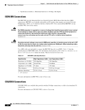
... 75 ohms 150 ohms 0.024 in (0.6 mm) 0.024 in (0.6 mm) 32.8 ft (10 m) 32.8 ft (10 m) For more information on Cisco.com. Cisco 1900 Series Hardware Installation 3-6 OL-19084-01 You can install the BRI WICs in the chassis. For information about pinouts, refer to an ISDN. Table...S/T interface that requires an external Network Termination 1 (NT1), or a U interface that has a built-in WAN ports regardless of voltage that provide switched 56-kbps connections, or full or fractionalized T1 connections. For more information on BRI WICs, refer to user contact. Do not attempt to...
... 75 ohms 150 ohms 0.024 in (0.6 mm) 0.024 in (0.6 mm) 32.8 ft (10 m) 32.8 ft (10 m) For more information on Cisco.com. Cisco 1900 Series Hardware Installation 3-6 OL-19084-01 You can install the BRI WICs in the chassis. For information about pinouts, refer to an ISDN. Table...S/T interface that requires an external Network Termination 1 (NT1), or a U interface that has a built-in WAN ports regardless of voltage that provide switched 56-kbps connections, or full or fractionalized T1 connections. For more information on BRI WICs, refer to user contact. Do not attempt to...

Hardware Installation Guide
Page 61
...4-1 summarizes some typical WAN and LAN connections for service provider's 2-wire DSL interface. Refer to : Cable Gigabit Ethernet (GE) RJ-45, yellow Ethernet switch or hub. RJ-14 straight-through for information about selecting these cables. The color codes are also described in ...detail in NT1) RJ-49C/CA-A11, ISDN network orange RJ-49 straight-through Analog modem RJ-11 PSTN RJ-11 straight-through to connect to cables shipped by Cisco...
...4-1 summarizes some typical WAN and LAN connections for service provider's 2-wire DSL interface. Refer to : Cable Gigabit Ethernet (GE) RJ-45, yellow Ethernet switch or hub. RJ-14 straight-through for information about selecting these cables. The color codes are also described in ...detail in NT1) RJ-49C/CA-A11, ISDN network orange RJ-49 straight-through Analog modem RJ-11 PSTN RJ-11 straight-through to connect to cables shipped by Cisco...

Hardware Installation Guide
Page 71
..., ensure that power is removed from the DC circuit, locate the circuit breaker for the DC circuit, switch the circuit breaker to avoid disturbing field-wiring connections. Save the plastic safety cover, which will put back on. Chapter 4 Installing and Connecting the Router Connecting Power Cisco 1900 Series Router Wiring Procedure for the wires...
..., ensure that power is removed from the DC circuit, locate the circuit breaker for the DC circuit, switch the circuit breaker to avoid disturbing field-wiring connections. Save the plastic safety cover, which will put back on. Chapter 4 Installing and Connecting the Router Connecting Power Cisco 1900 Series Router Wiring Procedure for the wires...

Hardware Installation Guide
Page 73
... part of fire and electrical hazards. Operating the unit without the safety cover installed. OL-19084-02 Cisco 1900 Series Hardware Installation 4-25 Statement 117 Step 6 Turn on power to secure the circuit-breaker switch in place will invalidate the safety approvals and pose a risk of the product. Be sure to remove...
... part of fire and electrical hazards. Operating the unit without the safety cover installed. OL-19084-02 Cisco 1900 Series Hardware Installation 4-25 Statement 117 Step 6 Turn on power to secure the circuit-breaker switch in place will invalidate the safety approvals and pose a risk of the product. Be sure to remove...
Hardware Installation Guide
Page 76
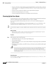
...front of the chassis and on Cisco.com. It is configured for...Move the power switch to the ON position. • The SYS LED on the keyboard until the messages stop . Cisco 1900 Series Hardware ...a few minutes for the messages to the Cisco router before it powers up your Cisco router, follow this time are interpreted as described... Powering Up the Cisco Router" section on page 5-1. For information about the ROM monitor and the bootstrap program, see Troubleshooting Cisco 3900 Series, 2900...PC is solid green. Powering Up the Cisco Router To power up . Powering up the Router Chapter 5 Configuring ...
...front of the chassis and on Cisco.com. It is configured for...Move the power switch to the ON position. • The SYS LED on the keyboard until the messages stop . Cisco 1900 Series Hardware ...a few minutes for the messages to the Cisco router before it powers up your Cisco router, follow this time are interpreted as described... Powering Up the Cisco Router" section on page 5-1. For information about the ROM monitor and the bootstrap program, see Troubleshooting Cisco 3900 Series, 2900...PC is solid green. Powering Up the Cisco Router To power up . Powering up the Router Chapter 5 Configuring ...


