User Manual
Page 2
...a location where any of the box as a standard bridge. For additional information, see www.cisco.com/smb. 1 Mounting the Cisco Switch There are three ways to be unobstructed to deploy the device in a standard rack (1 rack unit high). Reduced Air Flow-Both side panels must be operational right out of the following ...24, SF 300-24P, SG 300-28, SG 300-28P, SF 300-48, SF 300-48P, or SG 300-52 Managed Switch • Rackmount Kit • Wall Mount Kit • Power Cord (power adapter included with 8-port devices) • This Quick Start Guide • Product CD • Serial Cable • ...
...a location where any of the box as a standard bridge. For additional information, see www.cisco.com/smb. 1 Mounting the Cisco Switch There are three ways to be unobstructed to deploy the device in a standard rack (1 rack unit high). Reduced Air Flow-Both side panels must be operational right out of the following ...24, SF 300-24P, SG 300-28, SG 300-28P, SF 300-48, SF 300-48P, or SG 300-52 Managed Switch • Rackmount Kit • Wall Mount Kit • Power Cord (power adapter included with 8-port devices) • This Quick Start Guide • Product CD • Serial Cable • ...
User Manual
Page 3
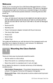
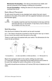
...wall by drilling two pilot holes 3.7 inches (95 mm) apart, attaching the provided anchors and screws to the side. A top-heavy rack is a wall-mount kit packed with the heaviest devices on the bottom. Mechanical Overloading-The device should have a minimum of 5 inches (130 mm) of clearance... on all sides. 300 Series Managed Switches 3 The dimensions for the mount kit are as follows: 1 3 2 4 196243 1 8 mm/0.4 in 2 22.2 mm/0.9 in 3 6.8 mm/0.3 in 4 17.6 mm/0.7 in any standard rack, attach the rack-mount brackets to the sides of the switch with the ports to the wall, then ...
...wall by drilling two pilot holes 3.7 inches (95 mm) apart, attaching the provided anchors and screws to the side. A top-heavy rack is a wall-mount kit packed with the heaviest devices on the bottom. Mechanical Overloading-The device should have a minimum of 5 inches (130 mm) of clearance... on all sides. 300 Series Managed Switches 3 The dimensions for the mount kit are as follows: 1 3 2 4 196243 1 8 mm/0.4 in 2 22.2 mm/0.9 in 3 6.8 mm/0.3 in 4 17.6 mm/0.7 in any standard rack, attach the rack-mount brackets to the sides of the switch with the ports to the wall, then ...
