Cisco CISCO815-VPN/K9 - 815 Integrated Services Router Support and Manuals
Get Help and Manuals for this Cisco item
View All Support Options Below
Free Cisco CISCO815-VPN/K9 manuals!
Problems with Cisco CISCO815-VPN/K9?
Ask a Question
Free Cisco CISCO815-VPN/K9 manuals!
Problems with Cisco CISCO815-VPN/K9?
Ask a Question
Popular Cisco CISCO815-VPN/K9 Manual Pages
Hardware Installation Guide - Page 6
... PC 2-17 Connecting the Power Supply 2-18
Mounting Your Router 2-18 Mounting on a Table 2-18 Mounting on a Wall 2-19
Verifying Installation 2-20 Where to Go from Here 2-22
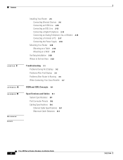
Troubleshooting 3-1 Problems During First Startup 3-2 Problems After First Startup 3-3 Problems After Router Is Running 3-5 When Contacting Your Cisco Reseller 3-7
ISDN and IDSL Concepts A-1
Specifications and Cables B-1 System...
Hardware Installation Guide - Page 16
... 804 routers.
2.
Eliminates need for troubleshooting. Supports Cisco IOS software. Wall-mount feature
All
Brackets on router bottom provide a way to terminal or PC for software configuration using command-line interface and for an external NT1 in place. You cannot connect S/T devices to IDSL network. Cisco 800 Series Routers Hardware Installation Guide
1-2
78-5373-04
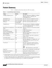
Feature...
Hardware Installation Guide - Page 18

...external NT1 or ISDN wall jack. Cisco 800 Series Routers Hardware Installation Guide
1-4
78-5373-04
HUB/NO HUB button
(for Ethernet port)
Console port
Determines cable
Connect PC or
type for Ethernet
terminal. device connection.
Ethernet port Connect Ethernet network device.
Locking power connector Connect power supply.
ISDN BRI S/T port Connect to physically...
Hardware Installation Guide - Page 19

... Connect to physically secure router.
Telephone ports Connect to physically secure router.
Power switch l = On.
= Standby or no power output.
PHONE
1 2
Locking power connector Connect power supply.
78-5373-04
Cisco 800 Series Routers Hardware Installation Guide
1-5 Power switch l = On.
= Standby or no power output.
11668
Cable lock Use cable lock to telephone, fax machine, or...
Hardware Installation Guide - Page 20

....
11669
Cable lock Use cable lock to physically secure router. Console port Connect PC or terminal. Locking power connector Connect power supply.
30771
Cisco 800 Series Routers Hardware Installation Guide
1-6
78-5373-04 HUB NO HUB
ETHERNET 10 BASE T 0
1 2 3
HUB/NO HUB button (for Ethernet port 0) Determines cable type for Ethernet device connection.
Back Panels
...
Hardware Installation Guide - Page 21

...Cisco 803 and 804 routers only. On when the Ethernet device is not connected. Blinks when the connection has a problem.
Cisco ...Troubleshooting" chapter.
78-5373-04
Cisco 800 Series Routers Hardware Installation Guide
1-7
Chapter 1 Overview
LEDs
Figure 1-9 Cisco 804 IDSL Router Back Panel
Ethernet ports Connect Ethernet network devices. Locking power connector Connect power supply...
Hardware Installation Guide - Page 26

... the following :
Cisco 800 Series Routers Hardware Installation Guide
2-4
78-5373-04
Connecting the port to a public network that follows the European Union standards.
Warning
If the symbol of public network can connect the port directly to the color-coded ports on the back panel.
• If you must supply your customer service representative. For more...
Hardware Installation Guide - Page 40
... a table or other end of the following guidelines:
2-18
Cisco 800 Series Routers Hardware Installation Guide
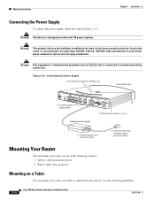
78-5373-04 Figure 2-10 Connecting the Power Supply 1.
Cisco 803
CONSOLE
ISDN S/T
PHONE 1
2
5. Connect other horizontal surface. Cisco 803 router
11673
HUB NO HUB
ETHERNET 10 BASE T
0 1 2 3
2. Connect power supply cable. Mounting Your Router
You can mount your router on...
Hardware Installation Guide - Page 41
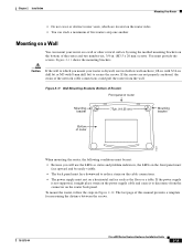
... supported, it might place strain on the power supply cable and cause it to secure the screws. The last page of five routers atop one another.
Mounting on a Wall
You can stack a maximum of this manual provides a template for measuring the distance between the screws.
78-5373-04
Cisco 800 Series Routers Hardware Installation Guide
2-19
Chapter 2 Installation...
Hardware Installation Guide - Page 42
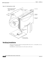
...on horizontal surface. Place power supply on , see Chapter 3, "Troubleshooting." Verifying Installation
Verify the cable connections (links) by checking the LEDs listed in .
(0.32
cm)
Screw
Maximum distance 6 ft (18 m)
11672
Chapter 2 Installation
Front panel
Mounting brackets 2. The LINK LED is on screws.
3.
Hang router on the back panel of Cisco 801 and Cisco 802 routers.
2-20...
Hardware Installation Guide - Page 46
Contact your Cisco reseller.
Cisco 800 Series Routers Hardware Installation Guide
3-2
78-5373-04
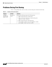
Solutions Perform the following steps in the following order: • Make sure that the power switch is ON. • Make sure that all connections to router. Table 3-1 Problems During First Startup
Symptom
All LEDs, including OK LED, are securely connected. • Make sure...
Hardware Installation Guide - Page 55
...power supply)
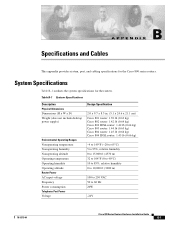
Environmental Operating Ranges Nonoperating temperature Nonoperating humidity Nonoperating altitude Operating temperature Operating humidity Operating altitude Router Power AC input voltage Frequency Power consumption Telephone Port Power Voltage
Design Specification
2.0 x 9.7 x 8.3 in. (5.1 x 24.6 x 21.1 cm) Cisco...78-5373-04
Cisco 800 Series Routers Hardware Installation Guide
B-1
Hardware Installation Guide - Page 67
...2-4 distances, maximum B-7 Ethernet, types 2-6 included with router 2-4 specifications B-6 caution statements, defined viii Cisco reseller, contacting 3-7 connecting analog telephone 2-15 digital telephone 2-14 Ethernet devices 2-6 fax 2-15 hubs 2-8 IDSL line 2-13 ISDN line 2-10 to 2-13
78-5373-04
INDEX
modem 2-15 PC 2-9, 2-17 power supply 2-18 server 2-9 telephones 2-14, 2-15 terminal or PC 2-17...
Hardware Installation Guide - Page 68
...L
LEDs
IN-2
Cisco 800 Series Routers Hardware Installation Guide
described 1-7 illustrated 1-3 to 1-6 locking power connector, illustrated 1-4 to 1-7
M
modem, connecting 2-15 mounting the router 2-18
N
network device button settings 2-6 to 2-7 NT1 feature 1-2
P
panels, illustrated 1-4 to 1-7 PC, connecting 2-9, 2-17 port connector pinouts B-2 to B-6 ports for specific routers 1-3 power
problems...
Hardware Installation Guide - Page 69

...PC button illustrated 1-6 to 1-7 settings 2-6 to 2-20 warnings, installation 2-2 weight specifications B-1 workstation, connecting 2-9
U
U interface A-1 United Kingdom master sockets 2-16
78-5373-04
Cisco 800 Series Routers Hardware Installation Guide
IN-3 to 2-4
V
voltage specifications B-1
W
wall brackets, illustrated 2-19 wall mounting 2-19 to 2-7 troubleshooting 3-1
unpacking the router...
Cisco CISCO815-VPN/K9 Reviews
We have not received any reviews for Cisco yet.