
User Guide
Page 4
... Installation Site 21 Unpack the Equipment 21 Installation Tasks 22 Mounting Kit 22 Mark the Rack 22 Install the Rails in the Rack 22 Rack-Mount the Switch 24 Installing the Switch Face Plate 25 Removing a Module or Blank 26 Installing the Spine and Leaf Modules ... SFS 7012 IP Address and Default Gateway via the CLI 30 Updating Management Spine IP Addresses in a Redundant Management Configuration 31 SFS 7012 Component LEDs 34 SFS 7012 Leaf and Spine Module LEDs 35 Accessing On-line Help 37 Shutdown Procedures 38 Rebooting Components from Chassis Viewer 38 Cisco SFS 7012 InfiniBand Server Switch...
... Installation Site 21 Unpack the Equipment 21 Installation Tasks 22 Mounting Kit 22 Mark the Rack 22 Install the Rails in the Rack 22 Rack-Mount the Switch 24 Installing the Switch Face Plate 25 Removing a Module or Blank 26 Installing the Spine and Leaf Modules ... SFS 7012 IP Address and Default Gateway via the CLI 30 Updating Management Spine IP Addresses in a Redundant Management Configuration 31 SFS 7012 Component LEDs 34 SFS 7012 Leaf and Spine Module LEDs 35 Accessing On-line Help 37 Shutdown Procedures 38 Rebooting Components from Chassis Viewer 38 Cisco SFS 7012 InfiniBand Server Switch...

User Guide
Page 20
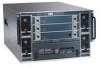
SFS 7012 Product Specifications Mechanical/Thermal/Power Specifications • 7U - 19" rack mount environment • Integrated thermal management • Front-to six (6), 350 Watt power supplies • 3.30" Width x 10.67" Depth x 1U height • 12V bulk power • Status indicators • Two (2) independent AC input lines Switch... Characteristics • 7U form factor • Full module enclosure • Available power (all copper): 745 Watts max Cisco SFS 7012 InfiniBand Server Switch Hardware Users Guide 2 Chapter OL-8787-04...
SFS 7012 Product Specifications Mechanical/Thermal/Power Specifications • 7U - 19" rack mount environment • Integrated thermal management • Front-to six (6), 350 Watt power supplies • 3.30" Width x 10.67" Depth x 1U height • 12V bulk power • Status indicators • Two (2) independent AC input lines Switch... Characteristics • 7U form factor • Full module enclosure • Available power (all copper): 745 Watts max Cisco SFS 7012 InfiniBand Server Switch Hardware Users Guide 2 Chapter OL-8787-04...
User Guide
Page 34
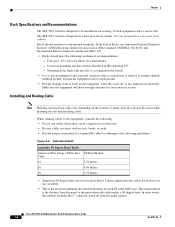
... be installed in IEC Standard 297 - Installing and Routing Cable Note Building and electrical codes vary depending on the equipment. Cisco SFS 7012 InfiniBand Server Switch Hardware Users Guide 16 OL-8787-04 Four-post, 19" rack to work site of any assembly. • This is the absolute minimum sustained bend radius for a two-post telco cabinet...
... be installed in IEC Standard 297 - Installing and Routing Cable Note Building and electrical codes vary depending on the equipment. Cisco SFS 7012 InfiniBand Server Switch Hardware Users Guide 16 OL-8787-04 Four-post, 19" rack to work site of any assembly. • This is the absolute minimum sustained bend radius for a two-post telco cabinet...

User Guide
Page 36
... of three categories: Note A textual callout designed to protect the system from potential damage. Cisco SFS 7012 InfiniBand Server Switch Hardware Users Guide 18 OL-8787-04 Mark the rack and install the mounting rails. Install intra-cabinet power and grounding cables for Rack-Mountable Products • Protecting Against Electrostatic Discharge • Electrical Safety Precautions Precautions fit into...
... of three categories: Note A textual callout designed to protect the system from potential damage. Cisco SFS 7012 InfiniBand Server Switch Hardware Users Guide 18 OL-8787-04 Mark the rack and install the mounting rails. Install intra-cabinet power and grounding cables for Rack-Mountable Products • Protecting Against Electrostatic Discharge • Electrical Safety Precautions Precautions fit into...

User Guide
Page 37
... supplies, is recommended that proper airflow is level and stable before touching any component from the rack. OL-8787-04 Cisco SFS 7012 InfiniBand Server Switch Hardware Users Guide 19 Caution Make sure the rack is provided to tip over . Chapter Precautions for Rack-Mountable Products Warning Installing system components in an antistatic container or packaging. Caution When transporting...
... supplies, is recommended that proper airflow is level and stable before touching any component from the rack. OL-8787-04 Cisco SFS 7012 InfiniBand Server Switch Hardware Users Guide 19 Caution Make sure the rack is provided to tip over . Chapter Precautions for Rack-Mountable Products Warning Installing system components in an antistatic container or packaging. Caution When transporting...

User Guide
Page 38
... service. Warning To avoid potential electrical shock, use only a grounded (three wire) electrical outlet. Caution Do not attempt to the rack. Warning Keep objects that might damage this unit and liquids that might cause damage. Liquids and foreign objects that might spill clear from... voltage points could create the risk of the branch circuit rating. To reduce the risk of action is to mark the mounting holes Cisco SFS 7012 InfiniBand Server Switch Hardware Users Guide 20 OL-8787-04 Tools and Equipment Required • An ESD wrist strap • A #2 Phillips screwdriver •...
... service. Warning To avoid potential electrical shock, use only a grounded (three wire) electrical outlet. Caution Do not attempt to the rack. Warning Keep objects that might damage this unit and liquids that might cause damage. Liquids and foreign objects that might spill clear from... voltage points could create the risk of the branch circuit rating. To reduce the risk of action is to mark the mounting holes Cisco SFS 7012 InfiniBand Server Switch Hardware Users Guide 20 OL-8787-04 Tools and Equipment Required • An ESD wrist strap • A #2 Phillips screwdriver •...
User Guide
Page 39
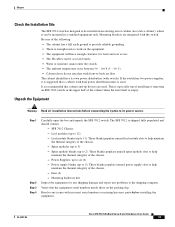
...removing an SFS 7012 switch in a standard equipment rack. Step 1 Step 2 Step 3 Step 4 Carefully open the box and unpack the SFS 7012 switch. These blanks populate unused spine module slots to 3) - Chapter Check the Installation Site The SFS 7012 switch is designed to be installed in an existing server cabinet (not... to 11). Unpack the Equipment Warning Read all installation instructions before installing the equipment. OL-8787-04 Cisco SFS 7012 InfiniBand Server Switch Hardware Users Guide 21 This is empty. These blanks populate unused leaf module slots to six (6) -...
...removing an SFS 7012 switch in a standard equipment rack. Step 1 Step 2 Step 3 Step 4 Carefully open the box and unpack the SFS 7012 switch. These blanks populate unused spine module slots to 3) - Chapter Check the Installation Site The SFS 7012 switch is designed to be installed in an existing server cabinet (not... to 11). Unpack the Equipment Warning Read all installation instructions before installing the equipment. OL-8787-04 Cisco SFS 7012 InfiniBand Server Switch Hardware Users Guide 21 This is empty. These blanks populate unused leaf module slots to six (6) -...
User Guide
Page 40
... flange of using the rails, a support shelf able to install the SFS 7012 switch in the rack. Fourteen caged nut adapters for square-holed racks Mark the Rack Allow 7U (12.25 inches) of the rack. Rack mount the switch. Mark the upper and lower mounting positions on the vertical rails on the... the vertical rails on the rack of the bottom of the necessary parts for use in the Rack Note The front flange (chassis fan side) of the rack. Install the Rails in cabinets with a depth ranging from 28 - 34 inches. Cisco SFS 7012 InfiniBand Server Switch Hardware Users Guide 22 OL-...
... flange of using the rails, a support shelf able to install the SFS 7012 switch in the rack. Fourteen caged nut adapters for square-holed racks Mark the Rack Allow 7U (12.25 inches) of the rack. Rack mount the switch. Mark the upper and lower mounting positions on the vertical rails on the... the vertical rails on the rack of the bottom of the necessary parts for use in the Rack Note The front flange (chassis fan side) of the rack. Install the Rails in cabinets with a depth ranging from 28 - 34 inches. Cisco SFS 7012 InfiniBand Server Switch Hardware Users Guide 22 OL-...

User Guide
Page 41
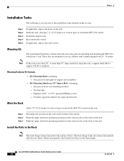
...caged nuts into the 2 back holes (chassis leaf module side) and the top and bottom holes (chassis fan side) in the front of the rack by repeating steps 1 through 3. Figure 5 Rail Front Flange Install 2 screws to the rail mounting positions (i.e., the holes marked with the top and...up with pen or tape). Fasten the rail back flange (chassis leaf module side) to the rack by installing two screws into the top hole of the rail front flange. OL-8787-04 Cisco SFS 7012 InfiniBand Server Switch Hardware Users Guide 23 Figure 4 Rail Back Flange Install 2 screws to top and bottom holes ...
...caged nuts into the 2 back holes (chassis leaf module side) and the top and bottom holes (chassis fan side) in the front of the rack by repeating steps 1 through 3. Figure 5 Rail Front Flange Install 2 screws to the rail mounting positions (i.e., the holes marked with the top and...up with pen or tape). Fasten the rail back flange (chassis leaf module side) to the rack by installing two screws into the top hole of the rail front flange. OL-8787-04 Cisco SFS 7012 InfiniBand Server Switch Hardware Users Guide 23 Figure 4 Rail Back Flange Install 2 screws to top and bottom holes ...

User Guide
Page 42
... any unnecessary materials. Caution Never lift the switch with the metal button against the skin. Chapter Rack-Mount the Switch Caution Because of its size and weight, it onto the rails. These handles are to support the weight of the SFS 7012. The fans and power supplies are on ...above and below the handle. Step 4 Tighten the screw on each rail Step 5 On each rail. Lift the switch and, from the front of the chassis; Cisco SFS 7012 InfiniBand Server Switch Hardware Users Guide 24 OL-8787-04 Figure 6 Secure Chassis to bare metal on the front of the cabinet, slide...
... any unnecessary materials. Caution Never lift the switch with the metal button against the skin. Chapter Rack-Mount the Switch Caution Because of its size and weight, it onto the rails. These handles are to support the weight of the SFS 7012. The fans and power supplies are on ...above and below the handle. Step 4 Tighten the screw on each rail Step 5 On each rail. Lift the switch and, from the front of the chassis; Cisco SFS 7012 InfiniBand Server Switch Hardware Users Guide 24 OL-8787-04 Figure 6 Secure Chassis to bare metal on the front of the cabinet, slide...
User Guide
Page 43
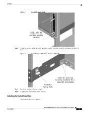
... to the ra assembly and chassis Installing the Switch Face Plate To install the switch face plate(s): OL-8787-04 Cisco SFS 7012 InfiniBand Server Switch Hardware Users Guide 25 If applicable, reinstall the chassis fascia(s). Install the lower rear mounting bracket to the rail assembly. Chapter Figure 7 Secure Chassis to Rack Install 1 screw and caged nut into each...
... to the ra assembly and chassis Installing the Switch Face Plate To install the switch face plate(s): OL-8787-04 Cisco SFS 7012 InfiniBand Server Switch Hardware Users Guide 25 If applicable, reinstall the chassis fascia(s). Install the lower rear mounting bracket to the rail assembly. Chapter Figure 7 Secure Chassis to Rack Install 1 screw and caged nut into each...
User Guide
Page 101
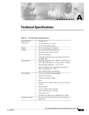
...per 300m to 2,000m • Non-operating temperature: -35°C to -back airflow • Active thermal performance monitoring switch board via IBML links • Operating temperature: 50° - 104°F (5° - 40°C) at sea level... IC Class B, ICES - 003 OL-8787-04 Cisco SFS 7012 InfiniBand Server Switch Hardware Users Guide 83 A A P P E N D I X Technical Specifications Table A-1 SFS 7012 Technical Specifications Switch Physical Dimensions Weight Cooling Environmental Power Supply Certification Marks • 7U high (24.5") • 19" rack mount (17.32" wide) • 25 3/4"...
...per 300m to 2,000m • Non-operating temperature: -35°C to -back airflow • Active thermal performance monitoring switch board via IBML links • Operating temperature: 50° - 104°F (5° - 40°C) at sea level... IC Class B, ICES - 003 OL-8787-04 Cisco SFS 7012 InfiniBand Server Switch Hardware Users Guide 83 A A P P E N D I X Technical Specifications Table A-1 SFS 7012 Technical Specifications Switch Physical Dimensions Weight Cooling Environmental Power Supply Certification Marks • 7U high (24.5") • 19" rack mount (17.32" wide) • 25 3/4"...