Cisco IPS-4260-K9 - IPS Sensor 4260 Support and Manuals
Get Help and Manuals for this Cisco item
View All Support Options Below
Free Cisco IPS-4260-K9 manuals!
Problems with Cisco IPS-4260-K9?
Ask a Question
Free Cisco IPS-4260-K9 manuals!
Problems with Cisco IPS-4260-K9?
Ask a Question
Cisco IPS-4260-K9 Videos

Cisco IPS 4260 Series Sensors
Duration: 3:11
Total Views: 4,092
Duration: 3:11
Total Views: 4,092
Popular Cisco IPS-4260-K9 Manual Pages
User Guide - Page 1

... Front and Back Panel Features, page 6-5 • Specifications, page 6-8 • Accessories, page 6-8 • Rack Mounting, page 6-9 • Installing IPS-4260, page 6-14 • Removing and Replacing the Chassis Cover, page 6-17 • Installing and Removing PCI Cards, page 6-19 • Installing and Removing the Power Supply, page 6-21
Caution
The BIOS on IPS-4260 voids the warranty.
User Guide - Page 2

... cards. It replaces IDS-4250-XL. Note The 1-Gbps performance for storage rather than 1 Gbps of 450 bytes, and the system running Cisco IPS 5.1 software. IPS-4260 ships with one power supply, but it supports redundant power supplies. For improved reliability, IPS-4260 uses a flash device for IPS-4260 is installed. IPS-4260 supports two optional network interface cards, the 2SX Fiber card...
User Guide - Page 4

... interface on IPS-4260:
• When bypass is set to AUTO (traffic flows without inspection), software bypass is powered off , reset, or if the NIC interface drivers fail or are set to support the hardware design of the card. If the sensor is activated if sensorApp fails. Hardware bypass complements the existing software bypass feature in hardware. Installing Cisco Intrusion...
User Guide - Page 5

...settings are associated in hardware as a bypass pair.
- Figure 6-3 shows the front view of the physical interfaces support hardware bypass.
- Figure 6-3
IPS-4260 Front Panel Features
RESET Power
POWER ID
Status
NIC Flash
RESET ID
ID
NIC POWER FLASH STATUS
Cisco IPS 4260 series
Intrusion Prevention Sensor
153095
ID
There are on the same interface card.
- OL-8677-01
Installing Cisco...
User Guide - Page 6

...)
4
Keyboard connector (not supported)
CONSOLE
GE 0/1
MGMT
Console Management
port
0/0
USB ports (not used)
Gigabit Ethernet 0/1
Video connector (not supported)
3 2 1
Power
Power
supply 2 supply 1
153094
Installing Cisco Intrusion Prevention System Appliances and Modules 5.1
6-6
OL-8677-01 Front and Back Panel Features
Chapter 6 Installing IPS-4260
Table 6-1 describes the front...
User Guide - Page 7

... indicator (for 1+1 configuration) or power supply critical event causing a...power supply off).
No AC power to this power supply (for TAC use)
Description Physical link Network activity 10 Mbps 100 Mbps 1000 Mbps
Status indicator
Table 6-3 lists the power supply indicator. OL-8677-01
Installing Cisco Intrusion Prevention System Appliances and Modules 5.1
6-7 Chapter 6 Installing IPS-4260...
User Guide - Page 8

...mountable
Power
...Accessories
Warning IMPORTANT SAFETY INSTRUCTIONS
This warning symbol means danger. Table 6-4
IPS-4260 Specifications
Dimensions...IPS-4260.
Statement 1071
SAVE THESE INSTRUCTIONS
Installing Cisco Intrusion Prevention System Appliances and Modules 5.1
6-8
OL-8677-01 Specifications
Chapter 6 Installing IPS-4260
Specifications
Table 6-4 lists the specifications...
User Guide - Page 9

...
ID
ID
NIC
POWER FLASH STATUS
Cisco IPSInt4ru2si6on0Prseeverniteiosn Sensor
153314
OL-8677-01
Installing Cisco Intrusion Prevention System Appliances and Modules 5.1
6-9
Statement 1030
IPS-4260 accessories kit contains the following topics: • Installing IPS-4260 in a 4-Post Rack, page 6-9 • Installing IPS-4260 in a 2-Post Rack, page 6-12
Installing IPS-4260 in a 4-Post Rack...
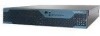
User Guide - Page 14

... to install, replace, or service this equipment.
To install IPS-4260 on the network, follow these steps by reading the safety warnings in an ESD environment, see Site and Safety Guidelines, page 1-23. Installing IPS-4260
Chapter 6 Installing IPS-4260
RESET
ID
ID
NIC
POWER FLASH STATUS
Cisco IPSInt4ru2si6on0Prseeverniteiosn Sensor
153324
Installing IPS-4260
Warning Only trained...
User Guide - Page 15
... from the accessory kit. Note Use the console port to connect to a computer to a power source (a UPS is the RJ-45 connector. The ground lug must comply with RJ-45 or hydra cable assembly connections. For the procedure, see Setting Up a Terminal Server, page 1-14. Attach the power cord to IPS-4260 and plug it .
Installing IPS-4260
153309
Note...
User Guide - Page 17

... ground conductor. For the procedure, see Initializing the Sensor, page 10-2. Configuring the Cisco Intrusion Prevention System Sensor Using the Command Line Interface
5.1
Removing and Replacing the Chassis Cover
Warning
This product relies on the building's installation for configuring intrusion prevention on IPS-4260. Statement 1005
Warning
This equipment must be grounded. Statement...
User Guide - Page 18

... Step 3 Step 4 Step 5
Step 6
Step 7
Power off :
sensor# reset powerdown
Wait for cooling the electronic components. Prepare IPS-4260 to IPS-4260. Caution
Do not operate IPS-4260 without the chassis cover installed. Removing and Replacing the Chassis Cover
Chapter 6 Installing IPS-4260
Note Removing the appliance chassis cover does not affect your Cisco warranty.
For more information, see...
User Guide - Page 19

...the CLI. IPS-4260 supports up to two network interface cards. If rack-mounted, remove IPS-4260 from IPS-4260. If you are reinstalling in an ESD-controlled environment. For an illustration of the supported PCI cards, see Rack Mounting, page 6-9. Step 3 Step 4 Step 5
Step 6
Step 7
Power off :
sensor# reset powerdown
Wait for the power down IPS-4260 using IDM. OL-8677-01
Installing Cisco...
User Guide - Page 21

... power supplies so that you are hot-swappable.
OL-8677-01
Installing Cisco Intrusion Prevention System Appliances and Modules 5.1
6-21
Note Power supplies are replacing a redundant power supply.
To install and remove power supplies, follow these steps:
Step 1 Step 2
Log in to be powered off IPS-4260. Step 3 Step 4
Power off :
sensor# reset powerdown
Wait for the power down IPS...
User Guide - Page 22

... 6 Installing IPS-4260
! ! Step 9 Power on IPS-4260.
6-22
Installing Cisco Intrusion Prevention System Appliances and Modules 5.1
OL-8677-01
Step 8 After installing or removing the power supply, replace the power cord and other cables. Installing and Removing the Power Supply
Step 6 Install the power supply. Step 7 To remove the power supply, push down the green tab and pull out the power...
Cisco IPS-4260-K9 Reviews
We have not received any reviews for Cisco yet.