
Hardware Installation Guide
Page 1
Cisco IE 3010 Switch Hardware Installation Guide August 2011 Americas Headquarters Cisco Systems, Inc. 170 West Tasman Drive San Jose, CA 95134-1706 USA http://www.cisco.com Tel: 408 526-4000 800 553-NETS (6387) Fax: 408 527-0883 Text Part Number: 78-19581-01
Cisco IE 3010 Switch Hardware Installation Guide August 2011 Americas Headquarters Cisco Systems, Inc. 170 West Tasman Drive San Jose, CA 95134-1706 USA http://www.cisco.com Tel: 408 526-4000 800 553-NETS (6387) Fax: 408 527-0883 Text Part Number: 78-19581-01

Hardware Installation Guide
Page 2
... are designed to which case users will not occur in a commercial environment. The Cisco implementation of Cisco's trademarks can radiate radio frequency energy and, if not installed and used in the U.S. IF YOU ARE UNABLE TO LOCATE THE SOFTWARE LICENSE OR... TCP header compression is likely to cause harmful interference, in which the receiver is operated in a particular installation. Cisco IE 3010 Switch Hardware Installation Guide © 2010-2011 Cisco Systems, Inc. THE SPECIFICATIONS AND INFORMATION REGARDING THE PRODUCTS IN THIS MANUAL ARE SUBJECT TO CHANGE WITHOUT NOTICE...
... are designed to which case users will not occur in a commercial environment. The Cisco implementation of Cisco's trademarks can radiate radio frequency energy and, if not installed and used in the U.S. IF YOU ARE UNABLE TO LOCATE THE SOFTWARE LICENSE OR... TCP header compression is likely to cause harmful interference, in which the receiver is operated in a particular installation. Cisco IE 3010 Switch Hardware Installation Guide © 2010-2011 Cisco Systems, Inc. THE SPECIFICATIONS AND INFORMATION REGARDING THE PRODUCTS IN THIS MANUAL ARE SUBJECT TO CHANGE WITHOUT NOTICE...

Hardware Installation Guide
Page 3
... Memory Card 1-11 Power-Supply Side 1-12 Power-Supply Side LEDs 1-13 Power Supply Features 1-14 Management Options 1-14 Network Configurations 1-14 78-19581-01 Cisco IE 3010 Switch Hardware Installation Guide iii
... Memory Card 1-11 Power-Supply Side 1-12 Power-Supply Side LEDs 1-13 Power Supply Features 1-14 Management Options 1-14 Network Configurations 1-14 78-19581-01 Cisco IE 3010 Switch Hardware Installation Guide iii

Hardware Installation Guide
Page 4
...13 Rack Mounting 2-14 Wall-Mounting 2-15 Attaching Brackets 2-16 Attaching Brackets (IP-30 Compliance) 2-16 Wall-Mounting 2-18 Installing and Removing SFP Modules 2-20 Installing SFP Modules 2-20 Removing SFP Modules 2-21 Inserting and...Installation 3-1 Power-Supply Modules 3-1 Power-Supply Module Installation 3-3 Installation Guidelines 3-3 Installing a Power-Supply Module 3-4 Equipment That You Need 3-4 Grounding the Switch 3-5 Installing the Power-Supply Module in the Switch 3-7 Wiring the Power Source 3-8 Removing the Power-Supply Module 3-13 Cisco IE 3010 Switch Hardware Installation Guide...
...13 Rack Mounting 2-14 Wall-Mounting 2-15 Attaching Brackets 2-16 Attaching Brackets (IP-30 Compliance) 2-16 Wall-Mounting 2-18 Installing and Removing SFP Modules 2-20 Installing SFP Modules 2-20 Removing SFP Modules 2-21 Inserting and...Installation 3-1 Power-Supply Modules 3-1 Power-Supply Module Installation 3-3 Installation Guidelines 3-3 Installing a Power-Supply Module 3-4 Equipment That You Need 3-4 Grounding the Switch 3-5 Installing the Power-Supply Module in the Switch 3-7 Wiring the Power Source 3-8 Removing the Power-Supply Module 3-13 Cisco IE 3010 Switch Hardware Installation Guide...

Hardware Installation Guide
Page 5
.../100 B-1 SFP Module Connectors B-2 Dual-Purpose Ports B-3 Alarm Port B-3 Cables and Adapters B-4 SFP Module Cables B-4 Cable Pinouts B-6 Console Port Adapter Pinouts B-7 Contents 78-19581-01 Cisco IE 3010 Switch Hardware Installation Guide v
.../100 B-1 SFP Module Connectors B-2 Dual-Purpose Ports B-3 Alarm Port B-3 Cables and Adapters B-4 SFP Module Cables B-4 Cable Pinouts B-6 Console Port Adapter Pinouts B-7 Contents 78-19581-01 Cisco IE 3010 Switch Hardware Installation Guide v

Hardware Installation Guide
Page 7
... you might do something that could result in a situation that you work on Cisco.com: http://www.cisco.com/go/IE3010_docs Note Means reader take note. Preface This guide describes the hardware features of each warning to install it, and provides troubleshooting information. Statement 1071 SAVE THESE INSTRUCTIONS 78-19581-01 Cisco IE 3010 Switch Hardware Installation Guide vii
... you might do something that could result in a situation that you work on Cisco.com: http://www.cisco.com/go/IE3010_docs Note Means reader take note. Preface This guide describes the hardware features of each warning to install it, and provides troubleshooting information. Statement 1071 SAVE THESE INSTRUCTIONS 78-19581-01 Cisco IE 3010 Switch Hardware Installation Guide vii
Hardware Installation Guide
Page 8
... guide. Cisco IE 3010 Switch Hardware Installation Guide viii 78-19581-01 Related Publications http://www.cisco.com/go/IE3010_docs Note Before installing, configuring, or upgrading the switch, see the release notes on Cisco.com for the latest information. • Release Notes for the Cisco IE 3010 Switch • Cisco IE 3010 Switch Getting Started Guide • Regulatory Compliance and Safety Information for the Cisco IE 3010 Switch • Cisco IE 3010...
... guide. Cisco IE 3010 Switch Hardware Installation Guide viii 78-19581-01 Related Publications http://www.cisco.com/go/IE3010_docs Note Before installing, configuring, or upgrading the switch, see the release notes on Cisco.com for the latest information. • Release Notes for the Cisco IE 3010 Switch • Cisco IE 3010 Switch Getting Started Guide • Regulatory Compliance and Safety Information for the Cisco IE 3010 Switch • Cisco IE 3010...
Hardware Installation Guide
Page 9
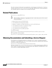
...8226; Management Options, page 1-14 Switch Models Table 1-1 Switch Models Model Description Cisco IE-3010-24TC Cisco IE-3010-16S-8PC 24 10/100 FastEthernet ports, 2 dual-purpose ports (2 10/100/1000BASE-T ...16 100BASE-FX SFP-module slots; 8 10/100 FastEthernet PoE2 ports, 2 dual-purpose ports (2 10/100/1000BASE-T copper ports and 2 SFP module slots), and 2 AC and DC power-supply module slots. 1. PoE = Power over Ethernet. 78-19581-01 Cisco IE 3010 Switch Hardware Installation Guide 1-1 It is suitable for harsh environments. Product Overview 1 C H A P T E R The Cisco IE 3010...
...8226; Management Options, page 1-14 Switch Models Table 1-1 Switch Models Model Description Cisco IE-3010-24TC Cisco IE-3010-16S-8PC 24 10/100 FastEthernet ports, 2 dual-purpose ports (2 10/100/1000BASE-T ...16 100BASE-FX SFP-module slots; 8 10/100 FastEthernet PoE2 ports, 2 dual-purpose ports (2 10/100/1000BASE-T copper ports and 2 SFP module slots), and 2 AC and DC power-supply module slots. 1. PoE = Power over Ethernet. 78-19581-01 Cisco IE 3010 Switch Hardware Installation Guide 1-1 It is suitable for harsh environments. Product Overview 1 C H A P T E R The Cisco IE 3010...

Hardware Installation Guide
Page 10
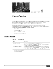
Figure 1-1 13 Cisco IE-3010-24TC Cable-Side View 5 67 8 208362 C isco IE 3010 2 4 9 1 SD1 flash memory card slot 2 LEDs 3 Express Setup button 4 10/100 ports 5 Dual purpose ports 1. Cable Side Chapter 1 Product Overview Cable Side The 10/100 ... 3 is above port 4, and so on the left. SD = Secure Digital 6 RJ-45 console port 7 USB (mini-Type B) console port 8 Power-input terminal 9 Alarm port Cisco IE 3010 Switch Hardware Installation Guide 1-2 78-19581-01
Figure 1-1 13 Cisco IE-3010-24TC Cable-Side View 5 67 8 208362 C isco IE 3010 2 4 9 1 SD1 flash memory card slot 2 LEDs 3 Express Setup button 4 10/100 ports 5 Dual purpose ports 1. Cable Side Chapter 1 Product Overview Cable Side The 10/100 ... 3 is above port 4, and so on the left. SD = Secure Digital 6 RJ-45 console port 7 USB (mini-Type B) console port 8 Power-input terminal 9 Alarm port Cisco IE 3010 Switch Hardware Installation Guide 1-2 78-19581-01
Hardware Installation Guide
Page 11
...-duplex transmission if the attached device supports it) and configures itself accordingly. Figure 1-2 13 Cisco IE-3010-16S-8PC Cable-Side View 5 6 78 9 208363 PO W ER OVER ETHERNET PO W ER OVER ETHERNET C isco IE 3010 2 4 10 1 SD flash memory card slot 2 LEDs 3 Express Setup button 4 ... interconnections are made aware of half duplex, full duplex, or 10 or 100 Mb/s. Statement 1072 78-19581-01 Cisco IE 3010 Switch Hardware Installation Guide 1-3 If the connected device also supports autonegotiation, the switch negotiates the best connection (the fastest line speed that present...
...-duplex transmission if the attached device supports it) and configures itself accordingly. Figure 1-2 13 Cisco IE-3010-16S-8PC Cable-Side View 5 6 78 9 208363 PO W ER OVER ETHERNET PO W ER OVER ETHERNET C isco IE 3010 2 4 10 1 SD flash memory card slot 2 LEDs 3 Express Setup button 4 ... interconnections are made aware of half duplex, full duplex, or 10 or 100 Mb/s. Statement 1072 78-19581-01 Cisco IE 3010 Switch Hardware Installation Guide 1-3 If the connected device also supports autonegotiation, the switch negotiates the best connection (the fastest line speed that present...
Hardware Installation Guide
Page 12
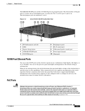
... switch deliver up to the Ethernet Ports" section on page 2-25 and the "Connector and Cable Specifications" section on page B-1. Cisco IE 3010 Switch Hardware Installation Guide 1-4 78-19581-01 The 100BASE-TX and 1000BASE-T traffic requires Category 5, Category 5e, or Category 6 unshielded twisted pair (UTP... see the switch software configuration guide on Cisco.com. The Cisco prestandard PoE is dropped, while power to support all the eight ports as PoE ports. Cable Side Chapter 1 Product Overview The 10/100 PoE ports on the Cisco IE-3010-16S-8PC switches provide PoE support for ...
... switch deliver up to the Ethernet Ports" section on page 2-25 and the "Connector and Cable Specifications" section on page B-1. Cisco IE 3010 Switch Hardware Installation Guide 1-4 78-19581-01 The 100BASE-TX and 1000BASE-T traffic requires Category 5, Category 5e, or Category 6 unshielded twisted pair (UTP... see the switch software configuration guide on Cisco.com. The Cisco prestandard PoE is dropped, while power to support all the eight ports as PoE ports. Cable Side Chapter 1 Product Overview The 10/100 PoE ports on the Cisco IE-3010-16S-8PC switches provide PoE support for ...

Hardware Installation Guide
Page 13
...-GE-Z with DOM support • GLC-EX-SMD with DOM support For information about SFP modules, see Appendix B, "SFP Module Cables." 78-19581-01 Cisco IE 3010 Switch Hardware Installation Guide 1-5 You can use any combination of SFP Module Rugged and Industrial SFPs -40 to 140°F (-40 to 60°C) Commercial SFPs 32 to...
...-GE-Z with DOM support • GLC-EX-SMD with DOM support For information about SFP modules, see Appendix B, "SFP Module Cables." 78-19581-01 Cisco IE 3010 Switch Hardware Installation Guide 1-5 You can use any combination of SFP Module Rugged and Industrial SFPs -40 to 140°F (-40 to 60°C) Commercial SFPs 32 to...

Hardware Installation Guide
Page 14
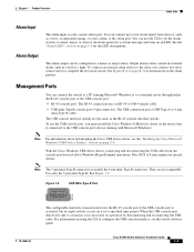
See Chapter 3, "Power Supply Installation," for the AC and DC power connections. The alarm is open or closed. • Open means that no current flows through the contact (referred to ... cable, a 0.5-meter, copper, passive cable with one or two power supplies. If one alarm output. The alarm setting is generated when the current flows. Cisco IE 3010 Switch Hardware Installation Guide 1-6 78-19581-01 You can operate with SFP module connectors at each end (see Figure 1-3). Power-Input Terminal The power-input terminal provides screw...
See Chapter 3, "Power Supply Installation," for the AC and DC power connections. The alarm is open or closed. • Open means that no current flows through the contact (referred to ... cable, a 0.5-meter, copper, passive cable with one or two power supplies. If one alarm output. The alarm setting is generated when the current flows. Cisco IE 3010 Switch Hardware Installation Guide 1-6 78-19581-01 You can operate with SFP module connectors at each end (see Figure 1-3). Power-Input Terminal The power-input terminal provides screw...
Hardware Installation Guide
Page 15
... complete the electrical circuit. They are the same as a bell or a light. See Figure 1-5. Cisco IE 3010 Switch Hardware Installation Guide 1-7 When the USB console port deactivates due to a timeout, you must install the Cisco Windows USB device driver on using the CLI to a terminal server through either the RJ-45 console ... connection uses a USB Type A-to the USB console port (device running Microsoft Windows or to configure the USB console interface, see the "Installing the Cisco Microsoft Windows USB Device Drivers" section on an LED. Use only the 5-pin mini-Type B.
... complete the electrical circuit. They are the same as a bell or a light. See Figure 1-5. Cisco IE 3010 Switch Hardware Installation Guide 1-7 When the USB console port deactivates due to a timeout, you must install the Cisco Windows USB device driver on using the CLI to a terminal server through either the RJ-45 console ... connection uses a USB Type A-to the USB console port (device running Microsoft Windows or to configure the USB console interface, see the "Installing the Cisco Microsoft Windows USB Device Drivers" section on an LED. Use only the 5-pin mini-Type B.
Hardware Installation Guide
Page 16
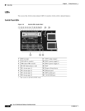
Switch Panel LEDs Figure 1-6 Switch LEDs (Cable Side) 1 2 3 4 5 6 7 8 9 10 11 12 13 207198 14 15 16 1 SYS (system) 2 CON (RJ-45 console) 3 USB (mini-USB console) 4 SD (SD flash memory card) 5 IN1 (alarm input 1) 6 IN2 (alarm input 2) 7 IN3 (alarm input ...system and port LEDs to monitor switch activity and performance. Only on the Cisco IE-3010-16S-8PC switch. 9 OUT (alarm output) 10 PSU1 (power supply 1) 11 PSU2 (power supply 2) 12 PoE1 13 Express Setup button 14 Ethernet ports 15 SFP module port 16 10/100/1000 port Cisco IE 3010 Switch Hardware Installation Guide 1-8 78-19581-01
Switch Panel LEDs Figure 1-6 Switch LEDs (Cable Side) 1 2 3 4 5 6 7 8 9 10 11 12 13 207198 14 15 16 1 SYS (system) 2 CON (RJ-45 console) 3 USB (mini-USB console) 4 SD (SD flash memory card) 5 IN1 (alarm input 1) 6 IN2 (alarm input 2) 7 IN3 (alarm input ...system and port LEDs to monitor switch activity and performance. Only on the Cisco IE-3010-16S-8PC switch. 9 OUT (alarm output) 10 PSU1 (power supply 1) 11 PSU2 (power supply 2) 12 PoE1 13 Express Setup button 14 Ethernet ports 15 SFP module port 16 10/100/1000 port Cisco IE 3010 Switch Hardware Installation Guide 1-8 78-19581-01

Hardware Installation Guide
Page 17
... Minor alarm Major alarm Critical alarm Table 1-6 Color Green Red Alarm Output LED System Status No alarm Relay closed, alarm present 78-19581-01 Cisco IE 3010 Switch Hardware Installation Guide 1-9 Power-Supply Module LEDs The switch power-supply module LEDs are receiving power. Blinking green POST1 is not functioning properly. 1. Green System is not...
... Minor alarm Major alarm Critical alarm Table 1-6 Color Green Red Alarm Output LED System Status No alarm Relay closed, alarm present 78-19581-01 Cisco IE 3010 Switch Hardware Installation Guide 1-9 Power-Supply Module LEDs The switch power-supply module LEDs are receiving power. Blinking green POST1 is not functioning properly. 1. Green System is not...

Hardware Installation Guide
Page 18
... about the individual ports. USB console port is not forwarding data. If you connect a cable to 30 seconds as STP searches for loops. 1-10 Cisco IE 3010 Switch Hardware Installation Guide 78-19581-01 After a port is reconfigured, the port LED is in use. Amber Port is blocked by Spanning Tree Protocol (STP) and is...
... about the individual ports. USB console port is not forwarding data. If you connect a cable to 30 seconds as STP searches for loops. 1-10 Cisco IE 3010 Switch Hardware Installation Guide 78-19581-01 After a port is reconfigured, the port LED is in use. Amber Port is blocked by Spanning Tree Protocol (STP) and is...

Hardware Installation Guide
Page 19
... Status SD flash memory card transfer in a replacement switch. SD flash memory card is detected (fast blinking). See Table 1-8 for information. 78-19581-01 Cisco IE 3010 Switch Hardware Installation Guide 1-11 You should not remove the card unless you can autonegotiate, or you want to reconfigure the new switch. Unsupported SD flash memory card...
... Status SD flash memory card transfer in a replacement switch. SD flash memory card is detected (fast blinking). See Table 1-8 for information. 78-19581-01 Cisco IE 3010 Switch Hardware Installation Guide 1-11 You should not remove the card unless you can autonegotiate, or you want to reconfigure the new switch. Unsupported SD flash memory card...

Hardware Installation Guide
Page 20
... 1-8 Switch with Both Power-Supply Modules P W R-R G D -LO W -D C P W R-R G D -LO W -D C 208375 CSwisictcohIES3e0ri1e0s 1 1 1 PSU OK LED For a description of the PSU OK LED, see Table 1-4 on page 1-9. 1-12 Cisco IE 3010 Switch Hardware Installation Guide 78-19581-01 See Figure 1-7 and Figure 1-8.
... 1-8 Switch with Both Power-Supply Modules P W R-R G D -LO W -D C P W R-R G D -LO W -D C 208375 CSwisictcohIES3e0ri1e0s 1 1 1 PSU OK LED For a description of the PSU OK LED, see Table 1-4 on page 1-9. 1-12 Cisco IE 3010 Switch Hardware Installation Guide 78-19581-01 See Figure 1-7 and Figure 1-8.
Hardware Installation Guide
Page 21
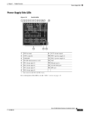
...Cisco IE-3010-16S-8PC switch. 9 OUT (alarm output) 10 PSU1 (power supply 1) 11 PSU2 (power supply 2) 12 PoE1 13 Ethernet port s 14 10/100/1000 port 15 SFP port For a description of the LEDs, see the "LEDs" section on page 1-8. 78-19581-01 Cisco IE 3010 Switch Hardware Installation Guide... 1-13 Chapter 1 Product Overview Power-Supply Side LEDs Figure 1-9 Switch LEDs 1 2 3 4 5 6 7 8 9 10 11 12 Cisco IE 3010 Switch Series Power-Supply Side 208364 13 14 15 1 SYS (system) 2 ...
...Cisco IE-3010-16S-8PC switch. 9 OUT (alarm output) 10 PSU1 (power supply 1) 11 PSU2 (power supply 2) 12 PoE1 13 Ethernet port s 14 10/100/1000 port 15 SFP port For a description of the LEDs, see the "LEDs" section on page 1-8. 78-19581-01 Cisco IE 3010 Switch Hardware Installation Guide... 1-13 Chapter 1 Product Overview Power-Supply Side LEDs Figure 1-9 Switch LEDs 1 2 3 4 5 6 7 8 9 10 11 12 Cisco IE 3010 Switch Series Power-Supply Side 208364 13 14 15 1 SYS (system) 2 ...


