Hardware Installation Guide
Page 15
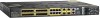
... device driver, see the switch software guide. Mac OS X or Linux require no input activity occurs on the alarm pinouts. See Figure 1-5. Cisco IE 3010 Switch Hardware Installation Guide 1-7 See the "Alarm LEDs" section on page C-4. The RJ-45 connection uses an RJ-45-to minor, major, ... reactivates the RJ-45 console port if the USB console port is activated, but no special drivers. You can connect the switch to a PC running with Microsoft Windows). Chapter 1 Product Overview Cable Side Alarm Input The alarm input is connected to complete the electrical circuit. To use ...
... device driver, see the switch software guide. Mac OS X or Linux require no input activity occurs on the alarm pinouts. See Figure 1-5. Cisco IE 3010 Switch Hardware Installation Guide 1-7 See the "Alarm LEDs" section on page C-4. The RJ-45 connection uses an RJ-45-to minor, major, ... reactivates the RJ-45 console port if the USB console port is activated, but no special drivers. You can connect the switch to a PC running with Microsoft Windows). Chapter 1 Product Overview Cable Side Alarm Input The alarm input is connected to complete the electrical circuit. To use ...

Hardware Installation Guide
Page 82
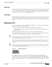
Figure B-8 Switch 1 TP0+ 2 TP03 TP1+ 6 TP1- 4 TP2+ 5 TP27 TP3+ 8 TP3- 65274 Four Twisted-Pair Crossover Cable Schematics for 1000BASE-T Ports Router or PC 1 TP0+ 2 TP03 TP1+ 6 TP1- 4 TP2+ 5 TP27 TP3+ 8 TP3- H5579 Figure B-7 Switch 1 TP0+ 2 TP03 TP1+ 6 TP1- 4 TP2+ 5 TP27... and Cable Specifications Cable Pinouts Figure B-5 Switch 3 TD+ 6 TD- 1 RD+ 2 RD- H5578 Figure B-6 Switch 3 TD+ 6 TD- 1 RD+ 2 RD- Cisco IE 3010 Switch Hardware Installation Guide B-6 78-19581-01 Two Twisted-Pair Straight-Through Cable Schematic for 10/100 Ports Switch 3 TD+ 6 TD- 1 RD+ 2 RD- Two Twisted...
Figure B-8 Switch 1 TP0+ 2 TP03 TP1+ 6 TP1- 4 TP2+ 5 TP27 TP3+ 8 TP3- 65274 Four Twisted-Pair Crossover Cable Schematics for 1000BASE-T Ports Router or PC 1 TP0+ 2 TP03 TP1+ 6 TP1- 4 TP2+ 5 TP27 TP3+ 8 TP3- H5579 Figure B-7 Switch 1 TP0+ 2 TP03 TP1+ 6 TP1- 4 TP2+ 5 TP27... and Cable Specifications Cable Pinouts Figure B-5 Switch 3 TD+ 6 TD- 1 RD+ 2 RD- H5578 Figure B-6 Switch 3 TD+ 6 TD- 1 RD+ 2 RD- Cisco IE 3010 Switch Hardware Installation Guide B-6 78-19581-01 Two Twisted-Pair Straight-Through Cable Schematic for 10/100 Ports Switch 3 TD+ 6 TD- 1 RD+ 2 RD- Two Twisted...

Hardware Installation Guide
Page 83
...as the wire connected to -DB-25 female DTE adapter is described in Table B-2 and Table B-3. You can order this adapter from Cisco (part number ACS-DSBUASYN=). 78-19581-01 Cisco IE 3010 Switch Hardware Installation Guide B-7 Table B-2 Console Port Signaling Using a DB-9 Adapter Switch Console Port (DTE) Signal RTS DTR TxD GND... (part number ACS-DSBUASYN=). The wire connected to pin 2 on the left end should be the same color as the wire connected to a PC console port. Table B-2 lists the pinouts for the switch console port, RJ-45-to -DB-9 adapter cable, and the console device.
...as the wire connected to -DB-25 female DTE adapter is described in Table B-2 and Table B-3. You can order this adapter from Cisco (part number ACS-DSBUASYN=). 78-19581-01 Cisco IE 3010 Switch Hardware Installation Guide B-7 Table B-2 Console Port Signaling Using a DB-9 Adapter Switch Console Port (DTE) Signal RTS DTR TxD GND... (part number ACS-DSBUASYN=). The wire connected to pin 2 on the left end should be the same color as the wire connected to a PC console port. Table B-2 lists the pinouts for the switch console port, RJ-45-to -DB-9 adapter cable, and the console device.

Hardware Installation Guide
Page 85
... cable to the 9-pin serial port on the PC or the terminal. Before connecting the switch to the switch console port. Start the terminal-emulation program on the PC. Accessing the CLI Through the Console Port You can enter Cisco IOS commands and parameters through the CLI. The... such as HyperTerminal or ProcommPlus, makes communication between the switch and your PC or terminal possible. 78-19581-01 Cisco IE 3010 Switch Hardware Installation Guide C-1 To set up the switch by using Express Setup, see the Cisco IE 3010 Switch Getting Started Guide. Use one of the cable to a power ...
... cable to the 9-pin serial port on the PC or the terminal. Before connecting the switch to the switch console port. Start the terminal-emulation program on the PC. Accessing the CLI Through the Console Port You can enter Cisco IOS commands and parameters through the CLI. The... such as HyperTerminal or ProcommPlus, makes communication between the switch and your PC or terminal possible. 78-19581-01 Cisco IE 3010 Switch Hardware Installation Guide C-1 To set up the switch by using Express Setup, see the Cisco IE 3010 Switch Getting Started Guide. Use one of the cable to a power ...

Hardware Installation Guide
Page 86
The PC or terminal displays the bootloader sequence. Press Enter to the switch as described in the "Completing the Setup Program" section on page C-7. Cisco IE 3010 Switch Hardware Installation Guide C-2 78-19581-01 Follow the steps in Chapter 3, "Power Supply Installation." Accessing the CLI Through the Console Port Appendix C Configuring the ...
The PC or terminal displays the bootloader sequence. Press Enter to the switch as described in the "Completing the Setup Program" section on page C-7. Cisco IE 3010 Switch Hardware Installation Guide C-2 78-19581-01 Follow the steps in Chapter 3, "Power Supply Installation." Accessing the CLI Through the Console Port Appendix C Configuring the ...

Hardware Installation Guide
Page 87
... Manager. To identify the COM port assigned to the PC USB port. The program, frequently a PC application such as HyperTerminal or ProcommPlus, makes communication possible between the switch and your PC or terminal. 78-19581-01 Cisco IE 3010 Switch Hardware Installation Guide C-3 See Figure C-2. • "Installing the Cisco Microsoft Windows XP USB Driver" section on page...
... Manager. To identify the COM port assigned to the PC USB port. The program, frequently a PC application such as HyperTerminal or ProcommPlus, makes communication possible between the switch and your PC or terminal. 78-19581-01 Cisco IE 3010 Switch Hardware Installation Guide C-3 See Figure C-2. • "Installing the Cisco Microsoft Windows XP USB Driver" section on page...

Hardware Installation Guide
Page 88
... from the Cisco.com software download site. The PC or terminal displays the bootloader sequence. Click Install. The USB console port LED turns green, and the Found New Hardware Wizard appears. Click Install. The Ready to Install the Program window appears. Step 2 Step 3 Step 4 Double-click the setup.exe file. Cisco IE 3010 Switch Hardware...
... from the Cisco.com software download site. The PC or terminal displays the bootloader sequence. Click Install. The USB console port LED turns green, and the Found New Hardware Wizard appears. Click Install. The Ready to Install the Program window appears. Step 2 Step 3 Step 4 Double-click the setup.exe file. Cisco IE 3010 Switch Hardware...

Hardware Installation Guide
Page 89
... trust this program. Uninstalling the Cisco Microsoft Windows USB Drivers Uninstalling the Cisco Microsoft Windows XP and 2000 USB Driver The driver can download the driver file from Cisco.com, and unzip it. Connect the USB cable to the PC and to Cisco Virtual Com, and click Remove....When the Program Maintenance window appears, select the Remove radio button. Click Next. 78-19581-01 Cisco IE 3010 Switch Hardware Installation Guide C-5 Connect the USB cable to the PC and to complete the driver installation. Follow the instructions to the switch console port. Appendix C ...
... trust this program. Uninstalling the Cisco Microsoft Windows USB Drivers Uninstalling the Cisco Microsoft Windows XP and 2000 USB Driver The driver can download the driver file from Cisco.com, and unzip it. Connect the USB cable to the PC and to Cisco Virtual Com, and click Remove....When the Program Maintenance window appears, select the Remove radio button. Click Next. 78-19581-01 Cisco IE 3010 Switch Hardware Installation Guide C-5 Connect the USB cable to the PC and to complete the driver installation. Follow the instructions to the switch console port. Appendix C ...