Installation Guide
Page 1
Cisco IE 3000 Switch Hardware Installation Guide June 2008 Americas Headquarters Cisco Systems, Inc. 170 West Tasman Drive San Jose, CA 95134-1706 USA http://www.cisco.com Tel: 408 526-4000 800 553-NETS (6387) Fax: 408 527-0883 Text Part Number: OL-13017-01
Cisco IE 3000 Switch Hardware Installation Guide June 2008 Americas Headquarters Cisco Systems, Inc. 170 West Tasman Drive San Jose, CA 95134-1706 USA http://www.cisco.com Tel: 408 526-4000 800 553-NETS (6387) Fax: 408 527-0883 Text Part Number: OL-13017-01
Installation Guide
Page 2
... the University of California, Berkeley (UCB) as part of UCB's public domain version of actual IP addresses in illustrative content is not installed in a commercial environment. Cisco IE 3000 Switch Hardware Installation Guide © 2008 Cisco Systems, Inc. These specifications are designed to Increase Your Internet Quotient, TransPath, WebEx, and the WebEx logo are trademarks; The use...
... the University of California, Berkeley (UCB) as part of UCB's public domain version of actual IP addresses in illustrative content is not installed in a commercial environment. Cisco IE 3000 Switch Hardware Installation Guide © 2008 Cisco Systems, Inc. These specifications are designed to Increase Your Internet Quotient, TransPath, WebEx, and the WebEx logo are trademarks; The use...

Installation Guide
Page 3
... Dual-Purpose Port LEDs 1-11 Compact Flash Memory Card 1-11 Rear-Panel Description 1-12 Power Converter (Optional) 1-13 Management Options 1-14 Network Configurations 1-15 Switch Installation 2-1 Preparing for Installation 2-1 Warnings 2-2 Cisco IE 3000 Switch Hardware Installation Guide iii
... Dual-Purpose Port LEDs 1-11 Compact Flash Memory Card 1-11 Rear-Panel Description 1-12 Power Converter (Optional) 1-13 Management Options 1-14 Network Configurations 1-15 Switch Installation 2-1 Preparing for Installation 2-1 Warnings 2-2 Cisco IE 3000 Switch Hardware Installation Guide iii
Installation Guide
Page 4
...2-32 Wiring the External Alarms 2-33 Connecting Destination Ports 2-36 Connecting to 10/100 and 10/100/1000 Ports 2-36 Installing and Removing SFP Modules 2-37 Installing SFP Modules into SFP Module Slots 2-38 Removing SFP Modules from SFP Module Slots 2-40 Connecting to SFP Modules 2-41 ... the Power Converter 2-44 Attaching the Power Converter to the Switch 2-45 Installing the Power Converter on a DIN Rail, Wall, or Rack Adapter 2-46 Connecting the DC Power Clip 2-46 Connecting the Power Converter to an AC Power Source 2-47 Cisco IE 3000 Switch Hardware Installation Guide iv OL-13017-01
...2-32 Wiring the External Alarms 2-33 Connecting Destination Ports 2-36 Connecting to 10/100 and 10/100/1000 Ports 2-36 Installing and Removing SFP Modules 2-37 Installing SFP Modules into SFP Module Slots 2-38 Removing SFP Modules from SFP Module Slots 2-40 Connecting to SFP Modules 2-41 ... the Power Converter 2-44 Attaching the Power Converter to the Switch 2-45 Installing the Power Converter on a DIN Rail, Wall, or Rack Adapter 2-46 Connecting the DC Power Clip 2-46 Connecting the Power Converter to an AC Power Source 2-47 Cisco IE 3000 Switch Hardware Installation Guide iv OL-13017-01
Installation Guide
Page 5
... and Configuration 3-5 How to Recover Passwords 3-5 Finding the Switch Serial Number 3-6 Technical Specifications A-1 Installation In a Hazardous Environment B-1 Preparing for Installation B-1 Warnings B-2 North American Hazardous Location Approval B-5 EMC Environmental Conditions for Products Installed in the European Union B-5 Installation Guidelines B-5 Environment and Enclosure Guidelines: B-5 Other Guidelines B-6 Verifying Package Contents B-7 Adding Modules to the Switch B-8 Cisco IE 3000 Switch Hardware Installation Guide v
... and Configuration 3-5 How to Recover Passwords 3-5 Finding the Switch Serial Number 3-6 Technical Specifications A-1 Installation In a Hazardous Environment B-1 Preparing for Installation B-1 Warnings B-2 North American Hazardous Location Approval B-5 EMC Environmental Conditions for Products Installed in the European Union B-5 Installation Guidelines B-5 Environment and Enclosure Guidelines: B-5 Other Guidelines B-6 Verifying Package Contents B-7 Adding Modules to the Switch B-8 Cisco IE 3000 Switch Hardware Installation Guide v
Installation Guide
Page 6
...-Purpose Port B-46 Connecting to 100BASE-FX Ports B-48 Connecting the Switch to the Power Converter B-49 Attaching the Power Converter to the Switch B-49 Installing the Power Converter on a DIN Rail, Wall, or Rack Adapter B-52 Connecting the DC Power Clip B-52 Connecting the Power Converter to an AC Power... the AC Power Cord to the Power Converter B-54 Connecting the Power Converter to a DC Power Source B-57 Applying Power to the Power Converter B-59 Cisco IE 3000 Switch Hardware Installation Guide vi OL-13017-01
...-Purpose Port B-46 Connecting to 100BASE-FX Ports B-48 Connecting the Switch to the Power Converter B-49 Attaching the Power Converter to the Switch B-49 Installing the Power Converter on a DIN Rail, Wall, or Rack Adapter B-52 Connecting the DC Power Clip B-52 Connecting the Power Converter to an AC Power... the AC Power Cord to the Power Converter B-54 Connecting the Power Converter to a DC Power Source B-57 Applying Power to the Power Converter B-59 Cisco IE 3000 Switch Hardware Installation Guide vi OL-13017-01
Installation Guide
Page 7
...-Based Setup Program D-1 Accessing the CLI from the Console Port D-1 Entering the Initial Configuration Information D-2 IP Settings D-2 Completing the Setup Program D-2 Contents OL-13017-01 Cisco IE 3000 Switch Hardware Installation Guide vii
...-Based Setup Program D-1 Accessing the CLI from the Console Port D-1 Entering the Initial Configuration Information D-2 IP Settings D-2 Completing the Setup Program D-2 Contents OL-13017-01 Cisco IE 3000 Switch Hardware Installation Guide vii

Installation Guide
Page 9
... technician responsible for notes, cautions, and warnings. Caution Means reader be careful. OL-13017-01 Cisco IE 3000 Switch Hardware Installation Guide ix This guide does not describe system messages that could result in this situation, you might receive or how to install a switch, and provides troubleshooting information. Note Means reader take note. Notes contain helpful suggestions...
... technician responsible for notes, cautions, and warnings. Caution Means reader be careful. OL-13017-01 Cisco IE 3000 Switch Hardware Installation Guide ix This guide does not describe system messages that could result in this situation, you might receive or how to install a switch, and provides troubleshooting information. Note Means reader take note. Notes contain helpful suggestions...

Installation Guide
Page 10
... the translated safety warnings that could cause bodily injury. Use the statement number provided at : http://www.cisco.com/en/US/docs/general/whatsnew/whatsnew.html Cisco IE 3000 Switch Hardware Installation Guide x OL-13017-01 You are available from this device. Related Publications Before installing, configuring, or upgrading the switch, see the monthly What's New in...
... the translated safety warnings that could cause bodily injury. Use the statement number provided at : http://www.cisco.com/en/US/docs/general/whatsnew/whatsnew.html Cisco IE 3000 Switch Hardware Installation Guide x OL-13017-01 You are available from this device. Related Publications Before installing, configuring, or upgrading the switch, see the monthly What's New in...

Installation Guide
Page 11
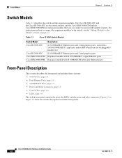
OL-13017-01 Cisco IE 3000 Switch Hardware Installation Guide 1-1 Overview 1 C H A P T E R This chapter provides these topics: • Overview, page 1-1 • Switch Models, page 1-2 • Front-Panel Description, page 1-2 • Compact Flash Memory Card, page 1-11 &#...
OL-13017-01 Cisco IE 3000 Switch Hardware Installation Guide 1-1 Overview 1 C H A P T E R This chapter provides these topics: • Overview, page 1-1 • Switch Models, page 1-2 • Front-Panel Description, page 1-2 • Compact Flash Memory Card, page 1-11 &#...
Installation Guide
Page 12
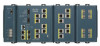
...expansion module front panels. Switch Models Chapter 1 Overview Switch Models Table 1-1 describes the switch and the expansion modules. Table 1-1 Cisco IE 3000 Switch Models Switch Model Cisco IE-3000-4TC Cisco IE-3000-8TC Cisco IEM-3000-8TM Cisco IEM-3000-8FM Description 4 10/100BASE-T Ethernet ports and 2 dual-purpose ports, each with a 10/100/1000BASE-T copper port and an... • Console Port, page 1-6 • LEDs, page 1-6 The switch front panel contains the ports, the LEDs, and the power and relay connectors. Cisco IE 3000 Switch Hardware Installation Guide 1-2 OL-13017-01
...expansion module front panels. Switch Models Chapter 1 Overview Switch Models Table 1-1 describes the switch and the expansion modules. Table 1-1 Cisco IE 3000 Switch Models Switch Model Cisco IE-3000-4TC Cisco IE-3000-8TC Cisco IEM-3000-8TM Cisco IEM-3000-8FM Description 4 10/100BASE-T Ethernet ports and 2 dual-purpose ports, each with a 10/100/1000BASE-T copper port and an... • Console Port, page 1-6 • LEDs, page 1-6 The switch front panel contains the ports, the LEDs, and the power and relay connectors. Cisco IE 3000 Switch Hardware Installation Guide 1-2 OL-13017-01
Installation Guide
Page 13
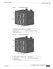
Chapter 1 Overview Figure 1-1 Cisco IE-3000-8TC Switch 1 2 Front-Panel Description 201699 3 45 1 Power and relay connectors 4 10/100 ports 2 Console port 5 Protective ground connection 3 Dual-purpose ports Figure 1-2 Cisco IE-3000-4TC Switch 1 2 201700 3 45 1 Power and relay connectors 4 2 Console port 5 3 Dual-purpose ports 10/100 ports Protective ground connection OL-13017-01 Cisco IE 3000 Switch Hardware Installation Guide 1-3
Chapter 1 Overview Figure 1-1 Cisco IE-3000-8TC Switch 1 2 Front-Panel Description 201699 3 45 1 Power and relay connectors 4 10/100 ports 2 Console port 5 Protective ground connection 3 Dual-purpose ports Figure 1-2 Cisco IE-3000-4TC Switch 1 2 201700 3 45 1 Power and relay connectors 4 2 Console port 5 3 Dual-purpose ports 10/100 ports Protective ground connection OL-13017-01 Cisco IE 3000 Switch Hardware Installation Guide 1-3
Installation Guide
Page 15
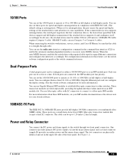
... (supply B) provides secondary power and the minor alarm signal. You can also set these SFP modules, see the switch software configuration guide or the switch command reference. You can use Category 3 or Category 4 cables. You can set the 10/100/1000 ports to...switch detects the required cable type for copper Ethernet connections and configures the interfaces accordingly. See Figure 1-2. OL-13017-01 Cisco IE 3000 Switch Hardware Installation Guide 1-5 For configuration information for this feature, see your SFP module documentation or the release note for your switch software....
... (supply B) provides secondary power and the minor alarm signal. You can also set these SFP modules, see the switch software configuration guide or the switch command reference. You can use Category 3 or Category 4 cables. You can set the 10/100/1000 ports to...switch detects the required cable type for copper Ethernet connections and configures the interfaces accordingly. See Figure 1-2. OL-13017-01 Cisco IE 3000 Switch Hardware Installation Guide 1-5 For configuration information for this feature, see your SFP module documentation or the release note for your switch software....
Installation Guide
Page 16
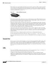
... source with the higher voltage. LEDs You can get replacement power and relay connectors (PWR-IE3000-CNCT=) by calling Cisco Technical Support. Cisco IE 3000 Switch Hardware Installation Guide 1-6 OL-13017-01 Front-Panel Description Chapter 1 Overview The switch accessory pack includes the mating power and relay connectors... relays. When both alarm relays. Both alarm terminals on the power and relay connector are operational, the switch draws power from Cisco Systems. For console-port and adapter-pinout information, see the "Two Twisted-Pair Cable Pinouts" section on the front panel....
... source with the higher voltage. LEDs You can get replacement power and relay connectors (PWR-IE3000-CNCT=) by calling Cisco Technical Support. Cisco IE 3000 Switch Hardware Installation Guide 1-6 OL-13017-01 Front-Panel Description Chapter 1 Overview The switch accessory pack includes the mating power and relay connectors... relays. When both alarm relays. Both alarm terminals on the power and relay connector are operational, the switch draws power from Cisco Systems. For console-port and adapter-pinout information, see the "Two Twisted-Pair Cable Pinouts" section on the front panel....

Installation Guide
Page 17
Chapter 1 Overview Figure 1-6 1 2 3 4 LEDs on the Cisco IE 3000 Switch Front-Panel Description 201703 5 67 8 1 Express setup button 2 System LED 3 Alarm LED 4 Setup LED 5 Dual-purpose uplink port LED 6 Pwr B LED 7 Pwr A LED 8 Port LED Figure 1-7 LEDs on the Cisco IEM-3000-8TM Module 201706 1 1 10/100 port LED OL-13017-01 Cisco IE 3000 Switch Hardware Installation Guide 1-7
Chapter 1 Overview Figure 1-6 1 2 3 4 LEDs on the Cisco IE 3000 Switch Front-Panel Description 201703 5 67 8 1 Express setup button 2 System LED 3 Alarm LED 4 Setup LED 5 Dual-purpose uplink port LED 6 Pwr B LED 7 Pwr A LED 8 Port LED Figure 1-7 LEDs on the Cisco IEM-3000-8TM Module 201706 1 1 10/100 port LED OL-13017-01 Cisco IE 3000 Switch Hardware Installation Guide 1-7

Installation Guide
Page 18
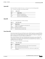
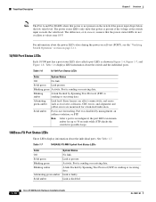
...) Solid green Blinking green Solid red Setup Status Switch is no available switch port to which to connect the management station. Switch is incomplete. Cisco IE 3000 Switch Hardware Installation Guide 1-8 OL-13017-01 Switch failed to start initial setup or recovery because there is configured as a managed switch. Switch is in recovery, or initial...
...) Solid green Blinking green Solid red Setup Status Switch is no available switch port to which to connect the management station. Switch is incomplete. Cisco IE 3000 Switch Hardware Installation Guide 1-8 OL-13017-01 Switch failed to start initial setup or recovery because there is configured as a managed switch. Switch is in recovery, or initial...
Installation Guide
Page 19
... shows whether the system is receiving power and is not functioning properly. If power is not present; If alarms are configured. OL-13017-01 Cisco IE 3000 Switch Hardware Installation Guide 1-9 Green Alarms are configured, the LED is red when power is not present, the LED color depends on the alarm configuration. Each DC input...
... shows whether the system is receiving power and is not functioning properly. If power is not present; If alarms are configured. OL-13017-01 Cisco IE 3000 Switch Hardware Installation Guide 1-9 Green Alarms are configured, the LED is red when power is not present, the LED color depends on the alarm configuration. Each DC input...
Installation Guide
Page 20
... "Verifying Switch Operation" section on the switch if the power input drops below the low valid level. Blinking green Activity. Link is disabled. 1-10 Cisco IE 3000 Switch Hardware Installation Guide OL-13017-01 Front-Panel Description Chapter 1 Overview Note The Pwr A and Pwr B LEDs show that the power status LEDs do not oscillate at...
... "Verifying Switch Operation" section on the switch if the power input drops below the low valid level. Blinking green Activity. Link is disabled. 1-10 Cisco IE 3000 Switch Hardware Installation Guide OL-13017-01 Front-Panel Description Chapter 1 Overview Note The Pwr A and Pwr B LEDs show that the power status LEDs do not oscillate at...
Installation Guide
Page 21
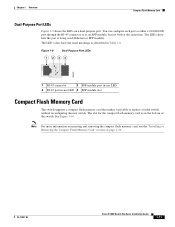
Note For more information on inserting and removing the compact flash memory card, see the "Installing or Removing the Compact Flash Memory Card" section on a dual-purpose port. The LEDs show how the port is on the bottom of the switch. ... as either a 10/100/1000 port through the RJ-45 connector or as described in -use LED 2 RJ-45 port in Table 1-6. OL-13017-01 Cisco IE 3000 Switch Hardware Installation Guide 1-11 The LED colors have the same meanings as an SFP module, but not both at the same time.
Note For more information on inserting and removing the compact flash memory card, see the "Installing or Removing the Compact Flash Memory Card" section on a dual-purpose port. The LEDs show how the port is on the bottom of the switch. ... as either a 10/100/1000 port through the RJ-45 connector or as described in -use LED 2 RJ-45 port in Table 1-6. OL-13017-01 Cisco IE 3000 Switch Hardware Installation Guide 1-11 The LED colors have the same meanings as an SFP module, but not both at the same time.
Installation Guide
Page 22
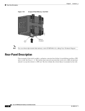
... Description Figure 1-10 Compact Flash Memory Card Slot Chapter 1 Overview 201832 Bottom 1 of the switch, modules, and power converter have latches for installation on the wall. 1-12 Cisco IE 3000 Switch Hardware Installation Guide OL-13017-01 The latches slide outward to position the switch over a DIN rail and slide inward to secure the switch to...
... Description Figure 1-10 Compact Flash Memory Card Slot Chapter 1 Overview 201832 Bottom 1 of the switch, modules, and power converter have latches for installation on the wall. 1-12 Cisco IE 3000 Switch Hardware Installation Guide OL-13017-01 The latches slide outward to position the switch over a DIN rail and slide inward to secure the switch to...


