
Installation Guide
Page 3
...Purpose ix Conventions ix Related Publications x Obtaining Documentation, Obtaining Support, and Security Guidelines x Overview 1-1 Overview 1-1 Switch Models 1-2 Front-Panel Description 1-2 10/100 Ports 1-5 Dual-Purpose Ports 1-5 100BASE-FX Ports 1-5 Power and Relay Connector 1-5 Console Port 1-6 LEDs 1-6 Setup ...Purpose Port LEDs 1-11 Compact Flash Memory Card 1-11 Rear-Panel Description 1-12 Power Converter (Optional) 1-13 Management Options 1-14 Network Configurations 1-15 Switch Installation 2-1 Preparing for Installation 2-1 Warnings 2-2 Cisco IE 3000 Switch Hardware Installation Guide iii
...Purpose ix Conventions ix Related Publications x Obtaining Documentation, Obtaining Support, and Security Guidelines x Overview 1-1 Overview 1-1 Switch Models 1-2 Front-Panel Description 1-2 10/100 Ports 1-5 Dual-Purpose Ports 1-5 100BASE-FX Ports 1-5 Power and Relay Connector 1-5 Console Port 1-6 LEDs 1-6 Setup ...Purpose Port LEDs 1-11 Compact Flash Memory Card 1-11 Rear-Panel Description 1-12 Power Converter (Optional) 1-13 Management Options 1-14 Network Configurations 1-15 Switch Installation 2-1 Preparing for Installation 2-1 Warnings 2-2 Cisco IE 3000 Switch Hardware Installation Guide iii

Installation Guide
Page 11
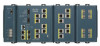
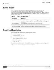
...; Overview, page 1-1 • Switch Models, page 1-2 • Front-Panel Description, page 1-2 • Compact Flash Memory Card, page 1-11 • Rear-Panel Description, page 1-12 • Power Converter (Optional), page 1-13 • Management Options, page 1-14 • Network Configurations, page 1-15 Overview The Cisco IE 3000 switch provides a rugged and secure switching infrastructure for industrial Ethernet...
...; Overview, page 1-1 • Switch Models, page 1-2 • Front-Panel Description, page 1-2 • Compact Flash Memory Card, page 1-11 • Rear-Panel Description, page 1-12 • Power Converter (Optional), page 1-13 • Management Options, page 1-14 • Network Configurations, page 1-15 Overview The Cisco IE 3000 switch provides a rugged and secure switching infrastructure for industrial Ethernet...
Installation Guide
Page 12
Table 1-1 Cisco IE 3000 Switch Models Switch Model Cisco IE-3000-4TC Cisco IE-3000-8TC Cisco IEM-3000-8TM Cisco IEM-3000-8FM Description 4 10/100BASE-T Ethernet ports and 2 dual-purpose ports, each with a 10/100/1000BASE-T copper port and an SFP (small form-factor pluggable) ... to the switch, see the "Adding Modules to Figure 1-4 show the switch and expansion module front panels. The Cisco IE-3000-4TC and the Cisco IE-3000-8TC are the switch models, and the Cisco IEM-3000-8TM and the Cisco IEM-3000-8FM are expansion modules that you can connect to increase the number of ports.
Table 1-1 Cisco IE 3000 Switch Models Switch Model Cisco IE-3000-4TC Cisco IE-3000-8TC Cisco IEM-3000-8TM Cisco IEM-3000-8FM Description 4 10/100BASE-T Ethernet ports and 2 dual-purpose ports, each with a 10/100/1000BASE-T copper port and an SFP (small form-factor pluggable) ... to the switch, see the "Adding Modules to Figure 1-4 show the switch and expansion module front panels. The Cisco IE-3000-4TC and the Cisco IE-3000-8TC are the switch models, and the Cisco IEM-3000-8TM and the Cisco IEM-3000-8FM are expansion modules that you can connect to increase the number of ports.
Installation Guide
Page 13
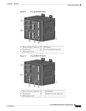
Chapter 1 Overview Figure 1-1 Cisco IE-3000-8TC Switch 1 2 Front-Panel Description 201699 3 45 1 Power and relay connectors 4 10/100 ports 2 Console port 5 Protective ground connection 3 Dual-purpose ports Figure 1-2 Cisco IE-3000-4TC Switch 1 2 201700 3 45 1 Power and relay connectors 4 2 Console port 5 3 Dual-purpose ports 10/100 ports Protective ground connection OL-13017-01 Cisco IE 3000 Switch Hardware Installation Guide 1-3
Chapter 1 Overview Figure 1-1 Cisco IE-3000-8TC Switch 1 2 Front-Panel Description 201699 3 45 1 Power and relay connectors 4 10/100 ports 2 Console port 5 Protective ground connection 3 Dual-purpose ports Figure 1-2 Cisco IE-3000-4TC Switch 1 2 201700 3 45 1 Power and relay connectors 4 2 Console port 5 3 Dual-purpose ports 10/100 ports Protective ground connection OL-13017-01 Cisco IE 3000 Switch Hardware Installation Guide 1-3
Installation Guide
Page 15
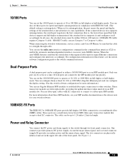
...about these ports for speed and duplex autonegotiation in compliance with LC connectors to connect to 1.24 miles (2 km) in length. OL-13017-01 Cisco IE 3000 Switch Hardware Installation Guide 1-5 In all cases, the attached device must be active at a time. For configuration information for autonegotiation, the port senses...minor alarm signal. When the auto-MDIX feature is , the fastest line speed that accepts a dual LC connector. Chapter 1 Overview Front-Panel Description 10/100 Ports You can set the 10/100 ports to operate at 10, 100, or 1000 Mb/s in full-duplex or half-duplex mode...
...about these ports for speed and duplex autonegotiation in compliance with LC connectors to connect to 1.24 miles (2 km) in length. OL-13017-01 Cisco IE 3000 Switch Hardware Installation Guide 1-5 In all cases, the attached device must be active at a time. For configuration information for autonegotiation, the port senses...minor alarm signal. When the auto-MDIX feature is , the fastest line speed that accepts a dual LC connector. Chapter 1 Overview Front-Panel Description 10/100 Ports You can set the 10/100 ports to operate at 10, 100, or 1000 Mb/s in full-duplex or half-duplex mode...
Installation Guide
Page 16
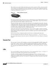
.... For console-port and adapter-pinout information, see Figure 1-5). LEDs You can be configured to complete an electrical circuit. Cisco IE 3000 Switch Hardware Installation Guide 1-6 OL-13017-01 Both alarm terminals on page C-5. If you want to connect a switch to a ...alarm relays. Console Port You can connect them . If one or with that adapter from the DC source with either open . Front-Panel Description Chapter 1 Overview The switch accessory pack includes the mating power and relay connectors. For more information about the power and relay connector, see...
.... For console-port and adapter-pinout information, see Figure 1-5). LEDs You can be configured to complete an electrical circuit. Cisco IE 3000 Switch Hardware Installation Guide 1-6 OL-13017-01 Both alarm terminals on page C-5. If you want to connect a switch to a ...alarm relays. Console Port You can connect them . If one or with that adapter from the DC source with either open . Front-Panel Description Chapter 1 Overview The switch accessory pack includes the mating power and relay connectors. For more information about the power and relay connector, see...

Installation Guide
Page 17
Chapter 1 Overview Figure 1-6 1 2 3 4 LEDs on the Cisco IE 3000 Switch Front-Panel Description 201703 5 67 8 1 Express setup button 2 System LED 3 Alarm LED 4 Setup LED 5 Dual-purpose uplink port LED 6 Pwr B LED 7 Pwr A LED 8 Port LED Figure 1-7 LEDs on the Cisco IEM-3000-8TM Module 201706 1 1 10/100 port LED OL-13017-01 Cisco IE 3000 Switch Hardware Installation Guide 1-7
Chapter 1 Overview Figure 1-6 1 2 3 4 LEDs on the Cisco IE 3000 Switch Front-Panel Description 201703 5 67 8 1 Express setup button 2 System LED 3 Alarm LED 4 Setup LED 5 Dual-purpose uplink port LED 6 Pwr B LED 7 Pwr A LED 8 Port LED Figure 1-7 LEDs on the Cisco IEM-3000-8TM Module 201706 1 1 10/100 port LED OL-13017-01 Cisco IE 3000 Switch Hardware Installation Guide 1-7

Installation Guide
Page 18
... available switch port to which to connect the management station. Cisco IE 3000 Switch Hardware Installation Guide 1-8 OL-13017-01 Switch is incomplete. Switch is in recovery, or initial setup is in initial setup, in initial setup. Front-Panel Description Figure 1-8 LEDs on the Cisco IEM-3000-8FM Module Chapter 1 Overview 201705 1 Setup LED 1 100BASE -FX...
... available switch port to which to connect the management station. Cisco IE 3000 Switch Hardware Installation Guide 1-8 OL-13017-01 Switch is incomplete. Switch is in recovery, or initial setup is in initial setup, in initial setup. Front-Panel Description Figure 1-8 LEDs on the Cisco IEM-3000-8FM Module Chapter 1 Overview 201705 1 Setup LED 1 100BASE -FX...
Installation Guide
Page 19
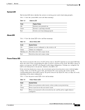
... LED colors and their meanings. Red Switch has detected a minor alarm. Table 1-5 lists the power status LED colors and meanings. OL-13017-01 Cisco IE 3000 Switch Hardware Installation Guide 1-9 System is green. Green Alarms are configured, the LED is red when power is off or red, depending on the ... one or two DC power sources. Power is functioning properly. Table 1-3 lists the system LED colors and their meanings. Chapter 1 Overview Front-Panel Description System LED The System LED shows whether the system is receiving power and is present on the associated circuit.
... LED colors and their meanings. Red Switch has detected a minor alarm. Table 1-5 lists the power status LED colors and meanings. OL-13017-01 Cisco IE 3000 Switch Hardware Installation Guide 1-9 System is green. Green Alarms are configured, the LED is red when power is off or red, depending on the ... one or two DC power sources. Power is functioning properly. Table 1-3 lists the system LED colors and their meanings. Chapter 1 Overview Front-Panel Description System LED The System LED shows whether the system is receiving power and is present on the associated circuit.
Installation Guide
Page 20
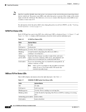
... below the low valid level. Solid green Link present. Blinking amber A link blocked by Spanning Tree Protocol (STP) is disabled. 1-10 Cisco IE 3000 Switch Hardware Installation Guide OL-13017-01 Table 1-7 100BASE-FX MM Uplink Port Status LEDs Color Off Solid green Blinking green Blinking amber Alternating...for a link-fault indication. The power status LEDs only show that power is present if the voltage at values near 18 V. Front-Panel Description Chapter 1 Overview Note The Pwr A and Pwr B LEDs show that the power status LEDs do not oscillate at the switch input exceeds...
... below the low valid level. Solid green Link present. Blinking amber A link blocked by Spanning Tree Protocol (STP) is disabled. 1-10 Cisco IE 3000 Switch Hardware Installation Guide OL-13017-01 Table 1-7 100BASE-FX MM Uplink Port Status LEDs Color Off Solid green Blinking green Blinking amber Alternating...for a link-fault indication. The power status LEDs only show that power is present if the voltage at values near 18 V. Front-Panel Description Chapter 1 Overview Note The Pwr A and Pwr B LEDs show that the power status LEDs do not oscillate at the switch input exceeds...
Installation Guide
Page 22
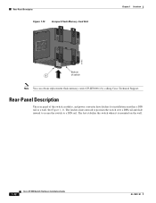
... Compact Flash Memory Card Slot Chapter 1 Overview 201832 Bottom 1 of the switch, modules, and power converter have latches for installation on the wall. 1-12 Cisco IE 3000 Switch Hardware Installation Guide OL-13017-01 Rear-Panel Description The rear panel of switch Note You can obtain replacement flash memory cards (CF-IE3000=) by calling...
... Compact Flash Memory Card Slot Chapter 1 Overview 201832 Bottom 1 of the switch, modules, and power converter have latches for installation on the wall. 1-12 Cisco IE 3000 Switch Hardware Installation Guide OL-13017-01 Rear-Panel Description The rear panel of switch Note You can obtain replacement flash memory cards (CF-IE3000=) by calling...

Installation Guide
Page 38
... between the switch and your terminal-emulation software is configured to the switch: Step 1 Step 2 Step 3 Make sure that adapter from Cisco. Follow these console-port default characteristics: • 9600 baud • Eight data bits • One stop bit • No parity...console port, you get access to the terminal, if needed. 2-12 Cisco IE 3000 Switch Hardware Installation Guide OL-13017-01 You can change the port baud rate. See the switch software configuration guide for pinout descriptions.) Figure 2-8 Connecting to the Console Port 201868 Step 4 Attach the...
... between the switch and your terminal-emulation software is configured to the switch: Step 1 Step 2 Step 3 Make sure that adapter from Cisco. Follow these console-port default characteristics: • 9600 baud • Eight data bits • One stop bit • No parity...console port, you get access to the terminal, if needed. 2-12 Cisco IE 3000 Switch Hardware Installation Guide OL-13017-01 You can change the port baud rate. See the switch software configuration guide for pinout descriptions.) Figure 2-8 Connecting to the Console Port 201868 Step 4 Attach the...
Installation Guide
Page 82
... for information about cabling, see if the problem follows the cable. Enable auto-MDIX on the network, an electrical arc can occur. Cisco IE 3000 Switch Hardware Installation Guide 3-2 OL-13017-01 Diagnosing Problems Chapter 3 Troubleshooting Warning If you connect or disconnect the console cable with a known...and use Category 3 copper cable for 10 Mb/s UTP connections Use either Category 5, Category 5e, or Category 6 UTP for a description of subtle damage to the switch or any bad patch panel connections or media convertors between the source and destination. This could corrupt ...
... for information about cabling, see if the problem follows the cable. Enable auto-MDIX on the network, an electrical arc can occur. Cisco IE 3000 Switch Hardware Installation Guide 3-2 OL-13017-01 Diagnosing Problems Chapter 3 Troubleshooting Warning If you connect or disconnect the console cable with a known...and use Category 3 copper cable for 10 Mb/s UTP connections Use either Category 5, Category 5e, or Category 6 UTP for a description of subtle damage to the switch or any bad patch panel connections or media convertors between the source and destination. This could corrupt ...

Installation Guide
Page 105
... control. This could cause an explosion in the console port. Be sure that adapter from Cisco. The PC or terminal must support VT100 terminal emulation. See the switch software configuration guide for pinout descriptions.) OL-13017-01 Cisco IE 3000 Switch Hardware Installation Guide B-15 For console-port and adapter-pinout information, see the "Cable...
... control. This could cause an explosion in the console port. Be sure that adapter from Cisco. The PC or terminal must support VT100 terminal emulation. See the switch software configuration guide for pinout descriptions.) OL-13017-01 Cisco IE 3000 Switch Hardware Installation Guide B-15 For console-port and adapter-pinout information, see the "Cable...
Installation Guide
Page 168
... to 2-43, B-46 to B-47 See 10/100 ports, 10/100/1000 ports, 100BASE-FX ports, 100BASE-LX ports, and console ports POST description 2-22, 2-53, 3-1, B-25, B-59 IN-4 Cisco IE 3000 Switch Hardware Installation Guide LEDs 3-1 results 2-22, 2-53, 3-1, B-25, B-59 running at power on 3-1 power connecting to AC 2-47, B-53 DC 2-16...
... to 2-43, B-46 to B-47 See 10/100 ports, 10/100/1000 ports, 100BASE-FX ports, 100BASE-LX ports, and console ports POST description 2-22, 2-53, 3-1, B-25, B-59 IN-4 Cisco IE 3000 Switch Hardware Installation Guide LEDs 3-1 results 2-22, 2-53, 3-1, B-25, B-59 running at power on 3-1 power connecting to AC 2-47, B-53 DC 2-16...

Software Configuration Guide
Page 13
... the Interface Speed and Duplex Parameters 13-14 Configuring IEEE 802.3x Flow Control 13-15 Configuring Auto-MDIX on an Interface 13-16 Adding a Description for an Interface 13-17 Configuring the System MTU 13-17 Monitoring and Maintaining the Interfaces 13-18 Monitoring Interface Status 13-19 Clearing and...-Range VLANs 15-4 Token Ring VLANs 15-5 Normal-Range VLAN Configuration Guidelines 15-5 VLAN Configuration Mode Options 15-6 VLAN Configuration in config-vlan Mode 15-6 Cisco IE 3000 Switch Software Configuration Guide xiii
... the Interface Speed and Duplex Parameters 13-14 Configuring IEEE 802.3x Flow Control 13-15 Configuring Auto-MDIX on an Interface 13-16 Adding a Description for an Interface 13-17 Configuring the System MTU 13-17 Monitoring and Maintaining the Interfaces 13-18 Monitoring Interface Status 13-19 Clearing and...-Range VLANs 15-4 Token Ring VLANs 15-5 Normal-Range VLAN Configuration Guidelines 15-5 VLAN Configuration Mode Options 15-6 VLAN Configuration in config-vlan Mode 15-6 Cisco IE 3000 Switch Software Configuration Guide xiii

Software Configuration Guide
Page 33
... concepts in this release. For information about the device manager, see Getting Started with Cisco Network Assistant, available on Cisco.com. OL-13018-03 Cisco IE 3000 Switch Software Configuration Guide xxxi Purpose This guide provides the information that have been created ... and vertical bars ( | ) separate the alternative elements. Conventions This publication uses these conventions to convey instructions and information: Command descriptions use these commands. For more information, see the release notes for this guide are in boldface text. • Arguments for use...
... concepts in this release. For information about the device manager, see Getting Started with Cisco Network Assistant, available on Cisco.com. OL-13018-03 Cisco IE 3000 Switch Software Configuration Guide xxxi Purpose This guide provides the information that have been created ... and vertical bars ( | ) separate the alternative elements. Conventions This publication uses these conventions to convey instructions and information: Command descriptions use these commands. For more information, see the release notes for this guide are in boldface text. • Arguments for use...

Software Configuration Guide
Page 59
... to configure configuration mode, parameters for each command mode. For example: Switch# sh conf Switch# show configuration OL-13018-03 Cisco IE 3000 Switch Software Configuration Guide 2-3 To return to privileged EXEC mode, press Ctrl-Z or enter end. To configure multiple interfaces with ...of the help abbreviated-command-entry? Use this mode to global configuration mode, enter exit. abbreviated-command-entry Purpose Obtain a brief description of associated keywords and arguments for the terminal line. ports. Obtain a list of Interfaces" section on page 13-4. Chapter 2...
... to configure configuration mode, parameters for each command mode. For example: Switch# sh conf Switch# show configuration OL-13018-03 Cisco IE 3000 Switch Software Configuration Guide 2-3 To return to privileged EXEC mode, press Ctrl-Z or enter end. To configure multiple interfaces with ...of the help abbreviated-command-entry? Use this mode to global configuration mode, enter exit. abbreviated-command-entry Purpose Obtain a brief description of associated keywords and arguments for the terminal line. ports. Obtain a list of Interfaces" section on page 13-4. Chapter 2...
Software Configuration Guide
Page 68
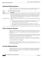
...Cisco IE 3000 Switch Software Configuration Guide 3-2 OL-13018-03 Understanding IE 3000 Switch Alarms Chapter 3 Configuring Cisco IE 3000 Switch Alarms Global Status Monitoring Alarms The IE 3000 switch can process alarms related to temperature and power supply conditions, referred to operate in Table 3-2. Table 3-1 IE 3000 Global Status Monitoring Alarms Alarm Power Supply Alarm Temperature Alarms Description... alarms, their descriptions, and functions. For more information, see the "Configuring the Switch Temperature Alarms" section on page 3-5. In the IE 3000 switch, the bit...
...Cisco IE 3000 Switch Software Configuration Guide 3-2 OL-13018-03 Understanding IE 3000 Switch Alarms Chapter 3 Configuring Cisco IE 3000 Switch Alarms Global Status Monitoring Alarms The IE 3000 switch can process alarms related to temperature and power supply conditions, referred to operate in Table 3-2. Table 3-1 IE 3000 Global Status Monitoring Alarms Alarm Power Supply Alarm Temperature Alarms Description... alarms, their descriptions, and functions. For more information, see the "Configuring the Switch Temperature Alarms" section on page 3-5. In the IE 3000 switch, the bit...

Software Configuration Guide
Page 69
.... See the "Configuring IE 3000 Switch Alarms" section on page 3-4 for this alarm is assigned a severity level based on configuring the relays. OL-13018-03 Cisco IE 3000 Switch Software Configuration Guide ...Cisco IOS System Error Message Severity Level. Each fault condition is assigned a severity level based on page 3-8 for triggering alarms: • Configurable Relays The switch is error condition, level 3. Table 3-2 IE 3000 Port Status Monitoring Alarms Alarm Link Fault alarm Port not Forwarding alarm Port not Operating alarm FCS Bit Error Rate alarm Description...
.... See the "Configuring IE 3000 Switch Alarms" section on page 3-4 for this alarm is assigned a severity level based on configuring the relays. OL-13018-03 Cisco IE 3000 Switch Software Configuration Guide ...Cisco IOS System Error Message Severity Level. Each fault condition is assigned a severity level based on page 3-8 for triggering alarms: • Configurable Relays The switch is error condition, level 3. Table 3-2 IE 3000 Port Status Monitoring Alarms Alarm Link Fault alarm Port not Forwarding alarm Port not Operating alarm FCS Bit Error Rate alarm Description...