Installation Guide
Page 4
Contents Installation Guidelines 2-3 Environment and Enclosure Guidelines: 2-3 Other Guidelines 2-3 Verifying Package Contents 2-5 Adding Modules to the Switch 2-5 Expansion Module Configurations 2-5 Connecting Modules 2-8 Installing or Removing the Compact Flash Memory Card 2-10 Verifying Switch Operation 2-11 Connecting a PC or a Terminal to the Console Port 2-... Converter on a DIN Rail, Wall, or Rack Adapter 2-46 Connecting the DC Power Clip 2-46 Connecting the Power Converter to an AC Power Source 2-47 Cisco IE 3000 Switch Hardware Installation Guide iv OL-13017-01
Contents Installation Guidelines 2-3 Environment and Enclosure Guidelines: 2-3 Other Guidelines 2-3 Verifying Package Contents 2-5 Adding Modules to the Switch 2-5 Expansion Module Configurations 2-5 Connecting Modules 2-8 Installing or Removing the Compact Flash Memory Card 2-10 Verifying Switch Operation 2-11 Connecting a PC or a Terminal to the Console Port 2-... Converter on a DIN Rail, Wall, or Rack Adapter 2-46 Connecting the DC Power Clip 2-46 Connecting the Power Converter to an AC Power Source 2-47 Cisco IE 3000 Switch Hardware Installation Guide iv OL-13017-01
Installation Guide
Page 6
Contents Expansion Module Configurations B-9 Connecting Modules B-11 Installing or Removing the Compact Flash Memory Card B-13 Verifying Switch Operation B-14 Connecting a PC or a Terminal to the Console ... the AC Power Cord to the Power Converter B-54 Connecting the Power Converter to a DC Power Source B-57 Applying Power to the Power Converter B-59 Cisco IE 3000 Switch Hardware Installation Guide vi OL-13017-01
Contents Expansion Module Configurations B-9 Connecting Modules B-11 Installing or Removing the Compact Flash Memory Card B-13 Verifying Switch Operation B-14 Connecting a PC or a Terminal to the Console ... the AC Power Cord to the Power Converter B-54 Connecting the Power Converter to a DC Power Source B-57 Applying Power to the Power Converter B-59 Cisco IE 3000 Switch Hardware Installation Guide vi OL-13017-01
Installation Guide
Page 12
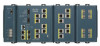
... the "Adding Modules to Figure 1-4 show the switch and expansion module front panels. Cisco IE 3000 Switch Hardware Installation Guide 1-2 OL-13017-01 For instructions on page 2-5. . The Cisco IE-3000-4TC and the Cisco IE-3000-8TC are the switch models, and the Cisco IEM-3000-8TM and the Cisco IEM-3000-8FM are expansion modules that you can connect to increase the number of...
... the "Adding Modules to Figure 1-4 show the switch and expansion module front panels. Cisco IE 3000 Switch Hardware Installation Guide 1-2 OL-13017-01 For instructions on page 2-5. . The Cisco IE-3000-4TC and the Cisco IE-3000-8TC are the switch models, and the Cisco IEM-3000-8TM and the Cisco IEM-3000-8FM are expansion modules that you can connect to increase the number of...
Installation Guide
Page 31
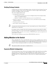
... device by 8 or 16, you can be either a Cisco IEM-3000-8TM or a Cisco IEM-3000-8FM. Adding Modules to the Switch The Cisco IE-3000-4TC or the Cisco IE-3000-8TC switch can connect the Cisco IEM-3000-8TM and the Cisco IEM-3000-8FM expansion modules. Expansion Module Configurations To increase the number of switches and expansion modules, you can operate as standalone devices. If...
... device by 8 or 16, you can be either a Cisco IEM-3000-8TM or a Cisco IEM-3000-8FM. Adding Modules to the Switch The Cisco IE-3000-4TC or the Cisco IE-3000-8TC switch can connect the Cisco IEM-3000-8TM and the Cisco IEM-3000-8FM expansion modules. Expansion Module Configurations To increase the number of switches and expansion modules, you can operate as standalone devices. If...
Installation Guide
Page 32
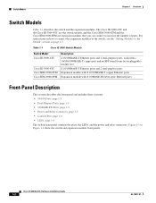
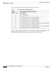
... and Expansion Modules Combination Cisco IE-3000-4TC 1 Cisco IE-3000-4TC 1 Cisco IE-3000-8TC 1 Cisco IE-3000-4TC and 1 Cisco IEM-3000-8FM 1 Cisco IE-3000-4TC and 1 Cisco IEM-3000-8TM 1 Cisco IE-3000-8TC and 1 Cisco IEM-3000-8FM 1 Cisco IE-3000-8TC and 1 Cisco IEM-3000-8TM 1 Cisco IE-3000-4TC and 1 Cisco IEM-3000-8TM and 1 Cisco IEM-3000-8FM 1 Cisco IE-3000-4TC and 2 Cisco IEM-3000-8TM 1 Cisco IE-3000-8TC and 1 Cisco IEM-3000-8TM and 1 Cisco IEM-3000-8FM 1 Cisco IE-3000-8TC and 2 Cisco IEM-3000-8TM Figure 2-1 shows example combinations of expansion modules can be used with a Cisco IE-3000-8TC...
... and Expansion Modules Combination Cisco IE-3000-4TC 1 Cisco IE-3000-4TC 1 Cisco IE-3000-8TC 1 Cisco IE-3000-4TC and 1 Cisco IEM-3000-8FM 1 Cisco IE-3000-4TC and 1 Cisco IEM-3000-8TM 1 Cisco IE-3000-8TC and 1 Cisco IEM-3000-8FM 1 Cisco IE-3000-8TC and 1 Cisco IEM-3000-8TM 1 Cisco IE-3000-4TC and 1 Cisco IEM-3000-8TM and 1 Cisco IEM-3000-8FM 1 Cisco IE-3000-4TC and 2 Cisco IEM-3000-8TM 1 Cisco IE-3000-8TC and 1 Cisco IEM-3000-8TM and 1 Cisco IEM-3000-8FM 1 Cisco IE-3000-8TC and 2 Cisco IEM-3000-8TM Figure 2-1 shows example combinations of expansion modules can be used with a Cisco IE-3000-8TC...

Installation Guide
Page 33
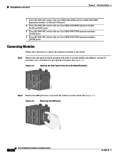
Chapter 2 Switch Installation Figure 2-1 Sample Combinations of Expansion Modules Adding Modules to the Switch 1 2 3 OL-13017-01 201827 4 Cisco IE 3000 Switch Hardware Installation Guide 2-7
Chapter 2 Switch Installation Figure 2-1 Sample Combinations of Expansion Modules Adding Modules to the Switch 1 2 3 OL-13017-01 201827 4 Cisco IE 3000 Switch Hardware Installation Guide 2-7
Installation Guide
Page 34
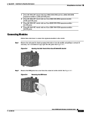
... Cisco IEM-3000-8TM expansion modules (12 FE ports) 4 Cisco IE-3000-4TC switch with two Cisco IEM-3000-8TM expansion modules (20 FE ports) Connecting Modules Follow these directions to connect the expansion modules to pry open the side panel. If necessary, use a screwdriver to the switch: Step 1 Remove the side panel by firmly grasping both sides of the Cisco IE-3000-8TC...
... Cisco IEM-3000-8TM expansion modules (12 FE ports) 4 Cisco IE-3000-4TC switch with two Cisco IEM-3000-8TM expansion modules (20 FE ports) Connecting Modules Follow these directions to connect the expansion modules to pry open the side panel. If necessary, use a screwdriver to the switch: Step 1 Remove the side panel by firmly grasping both sides of the Cisco IE-3000-8TC...

Installation Guide
Page 36
The switch ships with the compact flash memory card installed. You can connect another Cisco IEM-3000-8TM or Cisco IEM-3000-8FM expansion module. Follow Step 1 to Step 5 to connect the module. Installing or Removing the Compact Flash Memory Card Figure 2-6 Pushing the Module Latches In ... Verify that the card is in place on a removable flash memory card. Installing or Removing the Compact Flash Memory Card The switches store Cisco IOS software images and switch configurations on the bottom of the switch. 2-10 Cisco IE 3000 Switch Hardware Installation Guide OL-13017-01
The switch ships with the compact flash memory card installed. You can connect another Cisco IEM-3000-8TM or Cisco IEM-3000-8FM expansion module. Follow Step 1 to Step 5 to connect the module. Installing or Removing the Compact Flash Memory Card Figure 2-6 Pushing the Module Latches In ... Verify that the card is in place on a removable flash memory card. Installing or Removing the Compact Flash Memory Card The switches store Cisco IOS software images and switch configurations on the bottom of the switch. 2-10 Cisco IE 3000 Switch Hardware Installation Guide OL-13017-01

Installation Guide
Page 49
...described in . (90 mm) - Statement 1063 Caution To prevent the switch from accessibility to live parts. Cisco IE 3000 Switch Hardware Installation Guide 2-23 Figure 2-18 Cisco IE 3000 Switch Rear Panel 203976 OL-13017-01 You can install the switch as "open type" equipment. Front: ...the Wall • Installing the Switch in . (65 mm) Installing the Switch on a DIN Rail The switch ships with the expansion modules already connected. To connect the modules to prevent personal injury resulting from overheating, ensure these minimum clearances: - The interior of...
...described in . (90 mm) - Statement 1063 Caution To prevent the switch from accessibility to live parts. Cisco IE 3000 Switch Hardware Installation Guide 2-23 Figure 2-18 Cisco IE 3000 Switch Rear Panel 203976 OL-13017-01 You can install the switch as "open type" equipment. Front: ...the Wall • Installing the Switch in . (65 mm) Installing the Switch on a DIN Rail The switch ships with the expansion modules already connected. To connect the modules to prevent personal injury resulting from overheating, ensure these minimum clearances: - The interior of...

Installation Guide
Page 50
To attach the switch to install the switch as a standalone device. Step 1 Use a flathead screwdriver to press in this procedure show how to a DIN rail, follow these steps. See Figure 2-19. Figure 2-19 Unlock the Switch Latch 270302 2-24 Cisco IE 3000 Switch Hardware Installation Guide OL-13017-01 Installing the Switch Chapter 2 Switch Installation The illustrations in the space next to install a switch with expansion modules on each of the latches and turn the screw driver clockwise. The same steps can be used to the tab on the DIN rail.
To attach the switch to install the switch as a standalone device. Step 1 Use a flathead screwdriver to press in this procedure show how to a DIN rail, follow these steps. See Figure 2-19. Figure 2-19 Unlock the Switch Latch 270302 2-24 Cisco IE 3000 Switch Hardware Installation Guide OL-13017-01 Installing the Switch Chapter 2 Switch Installation The illustrations in the space next to install a switch with expansion modules on each of the latches and turn the screw driver clockwise. The same steps can be used to the tab on the DIN rail.

Installation Guide
Page 69
... page 2-1. Step 2 Insert one end of the cable to the other end of the fiber-optic cable into the SFP module port. OL-13017-01 Cisco IE 3000 Switch Hardware Installation Guide 2-43 For more information, see the switch command reference. Statement 1008 Caution Do not remove the rubber plugs from the SFF... port to a dual-purpose port and configures the port accordingly. Connecting to 100BASE-FX Ports Follow these steps to connect a fiber-optic cable to an Cisco IEM-3000-8FM expansion module: Warning Class 1 laser product.
... page 2-1. Step 2 Insert one end of the cable to the other end of the fiber-optic cable into the SFP module port. OL-13017-01 Cisco IE 3000 Switch Hardware Installation Guide 2-43 For more information, see the switch command reference. Statement 1008 Caution Do not remove the rubber plugs from the SFF... port to a dual-purpose port and configures the port accordingly. Connecting to 100BASE-FX Ports Follow these steps to connect a fiber-optic cable to an Cisco IEM-3000-8FM expansion module: Warning Class 1 laser product.

Installation Guide
Page 98
... cannot operate as standalone devices with four or eight Fast Ethernet ports, respectively. Cisco IE 3000 Switch Hardware Installation Guide B-8 OL-13017-01 To increase the number of switches and expansion modules, you can have up to the Switch Appendix B Installation In a Hazardous Environment For ...devices. Depending on a target device by 8 or 16, you can connect the Cisco IEM-3000-8TM and the Cisco IEM-3000-8FM expansion modules. Adding Modules to the Switch The Cisco IE-3000-4TC or the Cisco IE-3000-8TC switch can connect a 100BASE-FX port to a port on the mix of Fast ...
... cannot operate as standalone devices with four or eight Fast Ethernet ports, respectively. Cisco IE 3000 Switch Hardware Installation Guide B-8 OL-13017-01 To increase the number of switches and expansion modules, you can have up to the Switch Appendix B Installation In a Hazardous Environment For ...devices. Depending on a target device by 8 or 16, you can connect the Cisco IEM-3000-8TM and the Cisco IEM-3000-8FM expansion modules. Adding Modules to the Switch The Cisco IE-3000-4TC or the Cisco IE-3000-8TC switch can connect a 100BASE-FX port to a port on the mix of Fast ...
Installation Guide
Page 99
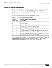
... Modules Combination Cisco IE-3000-4TC 1 Cisco IE-3000-4TC 1 Cisco IE-3000-8TC 1 Cisco IE-3000-4TC and 1 Cisco IEM-3000-8FM 1 Cisco IE-3000-4TC and 1 Cisco IEM-3000-8TM 1 Cisco IE-3000-8TC and 1 Cisco IEM-3000-8FM 1 Cisco IE-3000-8TC and 1 Cisco IEM-3000-8TM 1 Cisco IE-3000-4TC and 1 Cisco IEM-3000-8TM and 1 Cisco IEM-3000-8FM 1 Cisco IE-3000-4TC and 2 Cisco IEM-3000-8TM 1 Cisco IE-3000-8TC and 1 Cisco IEM-3000-8TM and 1 Cisco IEM-3000-8FM 1 Cisco IE-3000-8TC and 2 Cisco IEM-3000-8TM Figure B-1 shows example combinations of expansion modules can be used with a Cisco IE-3000-8TC switch. If...
... Modules Combination Cisco IE-3000-4TC 1 Cisco IE-3000-4TC 1 Cisco IE-3000-8TC 1 Cisco IE-3000-4TC and 1 Cisco IEM-3000-8FM 1 Cisco IE-3000-4TC and 1 Cisco IEM-3000-8TM 1 Cisco IE-3000-8TC and 1 Cisco IEM-3000-8FM 1 Cisco IE-3000-8TC and 1 Cisco IEM-3000-8TM 1 Cisco IE-3000-4TC and 1 Cisco IEM-3000-8TM and 1 Cisco IEM-3000-8FM 1 Cisco IE-3000-4TC and 2 Cisco IEM-3000-8TM 1 Cisco IE-3000-8TC and 1 Cisco IEM-3000-8TM and 1 Cisco IEM-3000-8FM 1 Cisco IE-3000-8TC and 2 Cisco IEM-3000-8TM Figure B-1 shows example combinations of expansion modules can be used with a Cisco IE-3000-8TC switch. If...

Installation Guide
Page 100
Adding Modules to the Switch Appendix B Installation In a Hazardous Environment Figure B-1 Sample Combinations of Expansion Modules 1 2 3 B-10 Cisco IE 3000 Switch Hardware Installation Guide 201827 4 OL-13017-01
Adding Modules to the Switch Appendix B Installation In a Hazardous Environment Figure B-1 Sample Combinations of Expansion Modules 1 2 3 B-10 Cisco IE 3000 Switch Hardware Installation Guide 201827 4 OL-13017-01
Installation Guide
Page 101
... Cisco IEM-3000-8TM expansion modules (12 FE ports) 4 Cisco IE-3000-4TC switch with two Cisco IEM-3000-8TM expansion modules (20 FE ports) Connecting Modules Follow these directions to connect the expansion modules to pry open the side panel. If necessary, use a screwdriver to the switch: Step 1 Remove the side panel by firmly grasping both sides of the Cisco IE-3000-8TC...
... Cisco IEM-3000-8TM expansion modules (12 FE ports) 4 Cisco IE-3000-4TC switch with two Cisco IEM-3000-8TM expansion modules (20 FE ports) Connecting Modules Follow these directions to connect the expansion modules to pry open the side panel. If necessary, use a screwdriver to the switch: Step 1 Remove the side panel by firmly grasping both sides of the Cisco IE-3000-8TC...

Installation Guide
Page 103
...Cisco IE 3000 Switch Hardware Installation Guide B-13 Appendix B Installation In a Hazardous Environment Installing or Removing the Compact Flash Memory Card Figure B-6 Pushing the Module Latches In 201826 Step 6 (Optional) If the first module attached was an Cisco IEM-3000-8TM, you can connect another Cisco IEM-3000-8TM or Cisco IEM-3000-8FM expansion... module. Installing or Removing the Compact Flash Memory Card The switches store Cisco IOS software images and ...
...Cisco IE 3000 Switch Hardware Installation Guide B-13 Appendix B Installation In a Hazardous Environment Installing or Removing the Compact Flash Memory Card Figure B-6 Pushing the Module Latches In 201826 Step 6 (Optional) If the first module attached was an Cisco IEM-3000-8TM, you can connect another Cisco IEM-3000-8TM or Cisco IEM-3000-8FM expansion... module. Installing or Removing the Compact Flash Memory Card The switches store Cisco IOS software images and ...

Installation Guide
Page 117
... B-27 To connect the modules to the switch, follow the steps described in this procedure show how to install a switch with expansion modules on the DIN rail. Figure B-18 Cisco IE 3000 Switch Rear Panel 203976 You can be used to install the switch as a standalone device on the DIN rail or with latches... install the switch as a standalone device. Appendix B Installation In a Hazardous Environment Installing the Switch Installing the Switch on a DIN Rail The switch ships with the expansion modules already connected. See Figure B-18.
... B-27 To connect the modules to the switch, follow the steps described in this procedure show how to install a switch with expansion modules on the DIN rail. Figure B-18 Cisco IE 3000 Switch Rear Panel 203976 You can be used to install the switch as a standalone device on the DIN rail or with latches... install the switch as a standalone device. Appendix B Installation In a Hazardous Environment Installing the Switch Installing the Switch on a DIN Rail The switch ships with the expansion modules already connected. See Figure B-18.

Installation Guide
Page 138
... "Cable and Adapter Specifications" section on the SFP module. Figure B-37 Connecting to the SFF module, be sure that you are ready to an Cisco IEM-3000-8FM expansion module: Warning Class 1 laser product. This process takes about the LC connector on page C-4 for future use. Step 2 Insert one end of the fiber... into the SFP module port. The LED turns amber while the STP discovers the network topology and searches for Installation" section on a target device. B-48 Cisco IE 3000 Switch Hardware Installation Guide OL-13017-01
... "Cable and Adapter Specifications" section on the SFP module. Figure B-37 Connecting to the SFF module, be sure that you are ready to an Cisco IEM-3000-8FM expansion module: Warning Class 1 laser product. This process takes about the LC connector on page C-4 for future use. Step 2 Insert one end of the fiber... into the SFP module port. The LED turns amber while the STP discovers the network topology and searches for Installation" section on a target device. B-48 Cisco IE 3000 Switch Hardware Installation Guide OL-13017-01

Software Configuration Guide
Page 180
The default PTP mode on all the Fast Ethernet and Gigabit Ethernet ports on the base switch module. The switch expansion modules do not support PTP. Default PTP Configuration Feature PTP boundary mode PTP forward mode PTP transparent mode PTP priority1 and PTP priority2 PTP announce .... Configuring PTP Chapter 9 Configuring PTP Default Configuration Table 9-1 By default, PTP is enabled on all ports is 128 2 seconds 8 seconds 32 seconds 1 second 50000 nanoseconds Cisco IE 3000 Switch Software Configuration Guide 9-2 OL-13018-03
The default PTP mode on all the Fast Ethernet and Gigabit Ethernet ports on the base switch module. The switch expansion modules do not support PTP. Default PTP Configuration Feature PTP boundary mode PTP forward mode PTP transparent mode PTP priority1 and PTP priority2 PTP announce .... Configuring PTP Chapter 9 Configuring PTP Default Configuration Table 9-1 By default, PTP is enabled on all ports is 128 2 seconds 8 seconds 32 seconds 1 second 50000 nanoseconds Cisco IE 3000 Switch Software Configuration Guide 9-2 OL-13018-03
Software Configuration Guide
Page 295
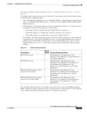
...The module number for a module that is connected to 3) depends on the switch. The module number for the IE-3000-4TC and IE-3000-8TC switches is connected to the switch or to the switch is 3. • Port number-The physical interface number... 13-1 Switch Interface Numbers Switch Model IE-3000-4TC switch IE-3000-8TC switch IEM-3000-8TM expansion module (connected to the switch) IEM-3000-8TM expansion module (connected to display information about a specific interface or all the interfaces. OL-13018-03 Cisco IE 3000 Switch Software Configuration Guide 13-5 To configure...
...The module number for a module that is connected to 3) depends on the switch. The module number for the IE-3000-4TC and IE-3000-8TC switches is connected to the switch or to the switch is 3. • Port number-The physical interface number... 13-1 Switch Interface Numbers Switch Model IE-3000-4TC switch IE-3000-8TC switch IEM-3000-8TM expansion module (connected to the switch) IEM-3000-8TM expansion module (connected to display information about a specific interface or all the interfaces. OL-13018-03 Cisco IE 3000 Switch Software Configuration Guide 13-5 To configure...