
Hardware Installation Guide
Page 6
...the Compliance Labels 7-9 Placing the Labels 7-10 Finding the Software Version 7-10 5-GHz Radio Module Upgrade 8-1 Upgrade Overview 8-2 Unpacking the Radio Module 8-2 Removing the 5-GHz Radio Access Cover 8-2 Removing a 5-GHz Radio Module 8-3 Installing a 5-GHz Radio Module 8-5 Attaching the Compliance Label 8-7 Finding the Software Version 8-8 Troubleshooting 9-1 Checking the Top ... 9-7 Using the MODE Button 9-7 Using the Web Browser Interface 9-8 Reloading the Access Point Image 9-8 Using the MODE button 9-9 Cisco Aironet 1200 Series Access Point Hardware Installation Guide vi OL-4310-05
...the Compliance Labels 7-9 Placing the Labels 7-10 Finding the Software Version 7-10 5-GHz Radio Module Upgrade 8-1 Upgrade Overview 8-2 Unpacking the Radio Module 8-2 Removing the 5-GHz Radio Access Cover 8-2 Removing a 5-GHz Radio Module 8-3 Installing a 5-GHz Radio Module 8-5 Attaching the Compliance Label 8-7 Finding the Software Version 8-8 Troubleshooting 9-1 Checking the Top ... 9-7 Using the MODE Button 9-7 Using the Web Browser Interface 9-8 Reloading the Access Point Image 9-8 Using the MODE button 9-9 Cisco Aironet 1200 Series Access Point Hardware Installation Guide vi OL-4310-05
Hardware Installation Guide
Page 10
... in boldface screen font. • Nonprinting characters, such as passwords or tabs, are in this publication. Chapter 8, "5-GHz Radio Module Upgrade," provides instructions for upgrading the access point 2.4-GHz radio. Appendix D, "Channels and Antenna Settings," lists the access point radio ... configure the access point. Conventions This publication uses these conventions to mount the access point on a desktop, wall, or ceiling. Cisco Aironet 1200 Series Access Point Hardware Installation Guide x OL-4310-05 Chapter 5, "Using the Command-Line Interface," describes how to use these ...
... in boldface screen font. • Nonprinting characters, such as passwords or tabs, are in this publication. Chapter 8, "5-GHz Radio Module Upgrade," provides instructions for upgrading the access point 2.4-GHz radio. Appendix D, "Channels and Antenna Settings," lists the access point radio ... configure the access point. Conventions This publication uses these conventions to mount the access point on a desktop, wall, or ceiling. Cisco Aironet 1200 Series Access Point Hardware Installation Guide x OL-4310-05 Chapter 5, "Using the Command-Line Interface," describes how to use these ...
Hardware Installation Guide
Page 19
... a 2.4-GHz radio (IEEE 802.11b or IEEE 802.11g) in an internal mini-PCI slot and a 5-GHz radio module (IEEE 802.11a) in an external, modified cardbus slot. Overview CH A P T E R 1 Cisco Aironet 1200 Series Access Points provide a ...secure, affordable, and easy-to the network. The access point supports one radio of a stand-alone wireless network. The access point serves as the connection point between wireless and wired networks or as the center point of each radio. This chapter provides information on Cisco IOS software, the 1200...
... a 2.4-GHz radio (IEEE 802.11b or IEEE 802.11g) in an internal mini-PCI slot and a 5-GHz radio module (IEEE 802.11a) in an external, modified cardbus slot. Overview CH A P T E R 1 Cisco Aironet 1200 Series Access Points provide a ...secure, affordable, and easy-to the network. The access point supports one radio of a stand-alone wireless network. The access point serves as the connection point between wireless and wired networks or as the center point of each radio. This chapter provides information on Cisco IOS software, the 1200...
Hardware Installation Guide
Page 20
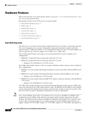
...modules. Note Cisco Aironet CB20A client radios can sometimes fail to associate to support dual-radio operation using a 5-GHz radio module or a 2.4-GHz mini-PCI radio card. Requires Cisco IOS Release 12.3(2)JA or later All 5-GHz radio modules incorporate an Unlicensed National Information Infrastructure (UNII) radio transceiver operating in three configurations: • IEEE 802.11a radio module...GHz), and channel 161 Cisco Aironet 1200 Series Access Point Hardware Installation Guide 1-2 OL-4310-05 The 802.11b or 802.11g radio is called Radio0 and the 802.11a radio is available in ...
...modules. Note Cisco Aironet CB20A client radios can sometimes fail to associate to support dual-radio operation using a 5-GHz radio module or a 2.4-GHz mini-PCI radio card. Requires Cisco IOS Release 12.3(2)JA or later All 5-GHz radio modules incorporate an Unlicensed National Information Infrastructure (UNII) radio transceiver operating in three configurations: • IEEE 802.11a radio module...GHz), and channel 161 Cisco Aironet 1200 Series Access Point Hardware Installation Guide 1-2 OL-4310-05 The 802.11b or 802.11g radio is called Radio0 and the 802.11a radio is available in ...
Hardware Installation Guide
Page 21
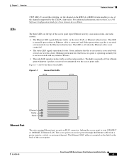
... cable is not associated with at least one of the channels supported by the CB20A client radio. OL-4310-05 Cisco Aironet 1200 Series Access Point Hardware Installation Guide 1-3 The Ethernet MAC address is received or transmitted over the Ethernet infrastructure. Figure ...activity. • The Ethernet LED signals Ethernet traffic on the RM21A or RM22A radio module to your 10BASE-T or 100BASE-T Ethernet LAN. For additional information, refer to the Cisco IOS Software Configuration Guide for Cisco Aironet Access Points. Chapter 1 Overview Hardware Features LEDs (5805 GHz).
... cable is not associated with at least one of the channels supported by the CB20A client radio. OL-4310-05 Cisco Aironet 1200 Series Access Point Hardware Installation Guide 1-3 The Ethernet MAC address is received or transmitted over the Ethernet infrastructure. Figure ...activity. • The Ethernet LED signals Ethernet traffic on the RM21A or RM22A radio module to your 10BASE-T or 100BASE-T Ethernet LAN. For additional information, refer to the Cisco IOS Software Configuration Guide for Cisco Aironet Access Points. Chapter 1 Overview Hardware Features LEDs (5805 GHz).
Hardware Installation Guide
Page 22
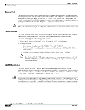
...the management system pages: 9600 baud, 8 data bits, No parity, 1 stop bit and no other power injectors or power modules have been tested to UL 2043 and they should not be placed in accordance with Section 300-22(c) of the console port pinouts...Cisco Aironet Power Injector (AIR-PWRINJ-FIB or AIR-PWRINJ3) - Hardware Features Chapter 1 Overview Console Port The console port provides access to the access point's command-line interface (CLI) using the Ethernet cable. An inline power patch panel, such as Cisco Catalyst 3500XL, 3550, 4500, or 6500 switches - Cisco Aironet 1200...
...the management system pages: 9600 baud, 8 data bits, No parity, 1 stop bit and no other power injectors or power modules have been tested to UL 2043 and they should not be placed in accordance with Section 300-22(c) of the console port pinouts...Cisco Aironet Power Injector (AIR-PWRINJ-FIB or AIR-PWRINJ3) - Hardware Features Chapter 1 Overview Console Port The console port provides access to the access point's command-line interface (CLI) using the Ethernet cable. An inline power patch panel, such as Cisco Catalyst 3500XL, 3550, 4500, or 6500 switches - Cisco Aironet 1200...
Hardware Installation Guide
Page 29
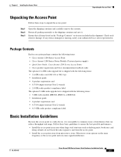
... Access Point • Cisco Aironet 1200 Series Power Module (Universal power supply) • Quick Start Guide: Cisco Aironet 1200 Series Access Points • Cisco product registration and Cisco documentation feedback cards The optional 2.4-GHz radio upgrade kit is shipped with the following items: • 2.4-GHz radio card (802.11b or 802.11g) • Installation guide • A product registration card • A T-10...
... Access Point • Cisco Aironet 1200 Series Power Module (Universal power supply) • Quick Start Guide: Cisco Aironet 1200 Series Access Points • Cisco product registration and Cisco documentation feedback cards The optional 2.4-GHz radio upgrade kit is shipped with the following items: • 2.4-GHz radio card (802.11b or 802.11g) • Installation guide • A product registration card • A T-10...
Hardware Installation Guide
Page 30
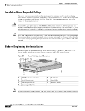
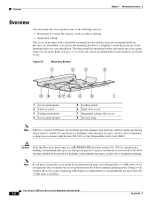
... the access point's layout, connectors, and 5-GHz module location. Before Beginning the Installation Before you begin the installation process, please refer to Figure 2-1, Figure 2-2, and Figure 2-3 to UL 2043 for operation in environmental air space, Cisco recommends that you plan to the Chapter 6, "Mounting Instructions." Cisco Aironet 1200 Series Access Point Hardware Installation Guide 2-4 OL-4310...
... the access point's layout, connectors, and 5-GHz module location. Before Beginning the Installation Before you begin the installation process, please refer to Figure 2-1, Figure 2-2, and Figure 2-3 to UL 2043 for operation in environmental air space, Cisco recommends that you plan to the Chapter 6, "Mounting Instructions." Cisco Aironet 1200 Series Access Point Hardware Installation Guide 2-4 OL-4310...

Hardware Installation Guide
Page 31
OL-4310-05 Cisco Aironet 1200 Series Access Point Hardware Installation Guide 2-5 Chapter 2 Installing the Access Point Before Beginning the Installation Figure 2-2 1 Access Point with 5-GHz Radio Module (RM20A or RM21A) 1 2 3 74631 1 Module mounting screws 2 Integrated antenna in patch position (RM20A or RM21A radio module) 3 Access point Figure 2-3 RM22A Radio Module with External RP-TNC Antenna Connectors ] 1 Left...
OL-4310-05 Cisco Aironet 1200 Series Access Point Hardware Installation Guide 2-5 Chapter 2 Installing the Access Point Before Beginning the Installation Figure 2-2 1 Access Point with 5-GHz Radio Module (RM20A or RM21A) 1 2 3 74631 1 Module mounting screws 2 Integrated antenna in patch position (RM20A or RM21A radio module) 3 Access point Figure 2-3 RM22A Radio Module with External RP-TNC Antenna Connectors ] 1 Left...

Hardware Installation Guide
Page 32
... 2.4-GHz Antennas The access point supports a single antenna or dual diversity antennas. To attach your access point has an installed RM22A radio module, connect a single antenna or dual diversity antennas (refer to the "Connecting the 5-GHz External Antennas" section on page 2-7). •...2.4-GHz antenna connectors (refer to Figure 2-1 for connector locations). Do not connect Cisco 5-GHz antennas with your antenna. If you are used for both the 2.4-GHz and 5-GHz radios. Cisco Aironet 1200 Series Access Point Hardware Installation Guide 2-6 OL-4310-05 Installation Summary Chapter 2 ...
... 2.4-GHz Antennas The access point supports a single antenna or dual diversity antennas. To attach your access point has an installed RM22A radio module, connect a single antenna or dual diversity antennas (refer to the "Connecting the 5-GHz External Antennas" section on page 2-7). •...2.4-GHz antenna connectors (refer to Figure 2-1 for connector locations). Do not connect Cisco 5-GHz antennas with your antenna. If you are used for both the 2.4-GHz and 5-GHz radios. Cisco Aironet 1200 Series Access Point Hardware Installation Guide 2-6 OL-4310-05 Installation Summary Chapter 2 ...

Hardware Installation Guide
Page 33
... have a blue marker label or blue dot near the antenna connector and the radio module has a corresponding blue label near the 5-GHz antenna connectors. Step 2 To mount your antenna. OL-4310-05 Cisco Aironet 1200 Series Access Point Hardware Installation Guide 2-7 If you are using two antennas for diversity coverage, attach the second antenna...
... have a blue marker label or blue dot near the antenna connector and the radio module has a corresponding blue label near the 5-GHz antenna connectors. Step 2 To mount your antenna. OL-4310-05 Cisco Aironet 1200 Series Access Point Hardware Installation Guide 2-7 If you are using two antennas for diversity coverage, attach the second antenna...
Hardware Installation Guide
Page 34
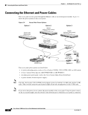
...AIR-PWRINJ3) • An inline power patch panel, such as the Cisco Catalyst Inline Power Patch Panel • A power module (Universal power supply) Note Currently, the Catalyst 3550-24 PWR switch supports power for the access point. Figure 2-4 shows the power options for both the 2.4-GHz radio and the 5-GHz radio. Cisco Aironet 1200... Series Access Point Hardware Installation Guide 2-8 OL-4310-05 Note If you use in-line power, do not connect the power module to which the access point is connected. Other switches ...
...AIR-PWRINJ3) • An inline power patch panel, such as the Cisco Catalyst Inline Power Patch Panel • A power module (Universal power supply) Note Currently, the Catalyst 3550-24 PWR switch supports power for the access point. Figure 2-4 shows the power options for both the 2.4-GHz radio and the 5-GHz radio. Cisco Aironet 1200... Series Access Point Hardware Installation Guide 2-8 OL-4310-05 Note If you use in-line power, do not connect the power module to which the access point is connected. Other switches ...

Hardware Installation Guide
Page 35
...Step 3 Step 4 Connect the Ethernet cable to the RJ-45 Ethernet connector labeled Ethernet on the access point. OL-4310-05 Cisco Aironet 1200 Series Access Point Hardware Installation Guide 2-9 Follow these steps to connect the access point to an Ethernet LAN when you must use...a building's environmental air space; Connecting to an Ethernet Network with your network. Connect the power module's output connector to UL 2043 for operation in a building's environmental air space, such as a Cisco Catalyst Inline Power Patch Panel. • The end of a Cisco Aironet power injector labeled To...
...Step 3 Step 4 Connect the Ethernet cable to the RJ-45 Ethernet connector labeled Ethernet on the access point. OL-4310-05 Cisco Aironet 1200 Series Access Point Hardware Installation Guide 2-9 Follow these steps to connect the access point to an Ethernet LAN when you must use...a building's environmental air space; Connecting to an Ethernet Network with your network. Connect the power module's output connector to UL 2043 for operation in a building's environmental air space, such as a Cisco Catalyst Inline Power Patch Panel. • The end of a Cisco Aironet power injector labeled To...
Hardware Installation Guide
Page 68
... the necessary mounting hardware. Cisco Aironet 1200 Series Access Point Hardware Installation Guide 6-2 OL-4310-05 Caution Only the fiber-optic power injector (AIR-PWRINJ-FIB) has been tested to mark the positions of the National Electrical Code (NEC). Because it is installed. no other power injectors or power modules have been tested to mount...
... the necessary mounting hardware. Cisco Aironet 1200 Series Access Point Hardware Installation Guide 6-2 OL-4310-05 Caution Only the fiber-optic power injector (AIR-PWRINJ-FIB) has been tested to mark the positions of the National Electrical Code (NEC). Because it is installed. no other power injectors or power modules have been tested to mount...
Hardware Installation Guide
Page 71
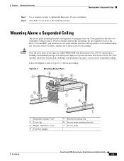
...above the tiles of a standard ceiling tile. Do not overtighten. You may be placed in a building's environmental air space; no other power injectors or power modules have been tested to UL 2043 for the antenna. Using a T-bar box hanger and bracket mounting clip (...2 1 95740 1 Suspended ceiling T-rail 2 T-rail clip 3 Height adjustment screw 4 T-bar box hanger 5 Bracket mounting clip 6 Access point mounting bracket 7 Access point OL-4310-05 Cisco Aironet 1200 Series Access Point Hardware Installation Guide 6-5 Step 8 Attach the access point to Figure 6-3 before proceeding.
...above the tiles of a standard ceiling tile. Do not overtighten. You may be placed in a building's environmental air space; no other power injectors or power modules have been tested to UL 2043 for the antenna. Using a T-bar box hanger and bracket mounting clip (...2 1 95740 1 Suspended ceiling T-rail 2 T-rail clip 3 Height adjustment screw 4 T-bar box hanger 5 Bracket mounting clip 6 Access point mounting bracket 7 Access point OL-4310-05 Cisco Aironet 1200 Series Access Point Hardware Installation Guide 6-5 Step 8 Attach the access point to Figure 6-3 before proceeding.

Hardware Installation Guide
Page 73
... end of the access point. OL-4310-05 Cisco Aironet 1200 Series Access Point Hardware Installation Guide 6-7 Insert the access point into the access point's 48-VDC power port. Slide the access point's mounting pins into place. If using local power, insert the 1200 series power module cable connector into the keyhole shaped holes and...
... end of the access point. OL-4310-05 Cisco Aironet 1200 Series Access Point Hardware Installation Guide 6-7 Insert the access point into the access point's 48-VDC power port. Slide the access point's mounting pins into place. If using local power, insert the 1200 series power module cable connector into the keyhole shaped holes and...

Hardware Installation Guide
Page 85
CH A P T E R 8 5-GHz Radio Module Upgrade This chapter provides upgrade instructions for a 5-GHz radio module and includes the following sections: • Upgrade Overview, page 8-2 • Removing the 5-GHz Radio Access Cover, page 8-2 • Removing a 5-GHz Radio Module, page 8-3 • Installing a 5-GHz Radio Module, page 8-5 OL-4310-05 Cisco Aironet 1200 Series Access Point Hardware Installation Guide 8-1
CH A P T E R 8 5-GHz Radio Module Upgrade This chapter provides upgrade instructions for a 5-GHz radio module and includes the following sections: • Upgrade Overview, page 8-2 • Removing the 5-GHz Radio Access Cover, page 8-2 • Removing a 5-GHz Radio Module, page 8-3 • Installing a 5-GHz Radio Module, page 8-5 OL-4310-05 Cisco Aironet 1200 Series Access Point Hardware Installation Guide 8-1

Hardware Installation Guide
Page 86
...radio module, you must be running Cisco IOS Release 12.3(2)JA or later before you upgrade to the Cisco IOS Software Configuration Guide for Cisco Aironet Access Points for upgrading the access point 5-GHz radio module (RM20A, RM21A, or RM22A). Refer to the RM21A or RM22A radio module;... the 5-GHz radio feature, remove the 5-GHz radio access cover. 4. Cisco Aironet 1200 Series Access Point Hardware Installation Guide 8-2 OL-4310-05 Upgrade Overview Chapter 8 5-GHz Radio Module Upgrade Upgrade Overview This section provides instructions for complete instructions on configuring the ...
...radio module, you must be running Cisco IOS Release 12.3(2)JA or later before you upgrade to the Cisco IOS Software Configuration Guide for Cisco Aironet Access Points for upgrading the access point 5-GHz radio module (RM20A, RM21A, or RM22A). Refer to the RM21A or RM22A radio module;... the 5-GHz radio feature, remove the 5-GHz radio access cover. 4. Cisco Aironet 1200 Series Access Point Hardware Installation Guide 8-2 OL-4310-05 Upgrade Overview Chapter 8 5-GHz Radio Module Upgrade Upgrade Overview This section provides instructions for complete instructions on configuring the ...

Hardware Installation Guide
Page 87
... 8-1 1 5-GHz Radio Access Cover 21 74632 1 Access Cover Screws 2 Access Cover Removing a 5-GHz Radio Module To remove the 5-GHz radio module, follow these steps: Step 1 Step 2 Step 3 Remove all cables and power connections from the module; OL-4310-05 Cisco Aironet 1200 Series Access Point Hardware Installation Guide 8-3 Place the access point on a flat surface so...
... 8-1 1 5-GHz Radio Access Cover 21 74632 1 Access Cover Screws 2 Access Cover Removing a 5-GHz Radio Module To remove the 5-GHz radio module, follow these steps: Step 1 Step 2 Step 3 Remove all cables and power connections from the module; OL-4310-05 Cisco Aironet 1200 Series Access Point Hardware Installation Guide 8-3 Place the access point on a flat surface so...

Hardware Installation Guide
Page 88
... antenna down (towards the attached radio card) and insert the module into a static protected bag. To install a new 5-GHz radio module, see Figure 8-3). Figure 8-3 Removing the 5-GHz Radio Module 74629 Step 5 Step 6 For a radio module with connectors, insert the radio module into a static protected bag. Cisco Aironet 1200 Series Access Point Hardware Installation Guide 8-4 OL-4310-05 Removing...
... antenna down (towards the attached radio card) and insert the module into a static protected bag. To install a new 5-GHz radio module, see Figure 8-3). Figure 8-3 Removing the 5-GHz Radio Module 74629 Step 5 Step 6 For a radio module with connectors, insert the radio module into a static protected bag. Cisco Aironet 1200 Series Access Point Hardware Installation Guide 8-4 OL-4310-05 Removing...


