Hardware Installation Guide
Page 7
..., conventions used in installing routers. Audience This guide is implemented on safety, preventing damage, unpacking, and preparing for service technicians with all technicians is to connect the router to additional information and material. 78-5373-04 Cisco 800 Series Routers Hardware Installation Guide vii Notes contain helpful suggestions or references to the network as quickly as installing, mounting, and verifying the connections to your router. • Troubleshooting-Describes...
..., conventions used in installing routers. Audience This guide is implemented on safety, preventing damage, unpacking, and preparing for service technicians with all technicians is to connect the router to additional information and material. 78-5373-04 Cisco 800 Series Routers Hardware Installation Guide vii Notes contain helpful suggestions or references to the network as quickly as installing, mounting, and verifying the connections to your router. • Troubleshooting-Describes...
Hardware Installation Guide
Page 10
...) feed from Cisco. security-alert@cisco.com • Nonemergencies - psirt@cisco.com Cisco 800 Series Routers Hardware Installation Guide x 78-5373-04 You can submit comments by using the response card (if present) behind the front cover of security advisories and notices for Cisco products is committed to receive security information from this URL: http://www.cisco.com/en/US/products/products_psirt_rss_feed.html Reporting Security Problems in Cisco Products Cisco is available...
...) feed from Cisco. security-alert@cisco.com • Nonemergencies - psirt@cisco.com Cisco 800 Series Routers Hardware Installation Guide x 78-5373-04 You can submit comments by using the response card (if present) behind the front cover of security advisories and notices for Cisco products is committed to receive security information from this URL: http://www.cisco.com/en/US/products/products_psirt_rss_feed.html Reporting Security Problems in Cisco Products Cisco is available...
Hardware Installation Guide
Page 11
... your product serial number before placing a service call. 78-5373-04 Cisco 800 Series Routers Hardware Installation Guide xi About This Guide Obtaining Technical Assistance Tip We encourage you to use a revoked or an expired encryption key. If you have a valid service contract but do Note Use the Cisco Product Identification (CPI) tool to locate your product with Cisco products and technologies. or for troubleshooting and...
... your product serial number before placing a service call. 78-5373-04 Cisco 800 Series Routers Hardware Installation Guide xi About This Guide Obtaining Technical Assistance Tip We encourage you to use a revoked or an expired encryption key. If you have a valid service contract but do Note Use the Cisco Product Identification (CPI) tool to locate your product with Cisco products and technologies. or for troubleshooting and...
Hardware Installation Guide
Page 16
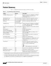
... services through ISDN line. Locking power connector All Locks power connector in a different color from other LEDs. Although the ISDN U interfaces on router bottom provide a way to ISDN U network. Cisco 800 Series Routers Hardware Installation Guide 1-2 78-5373-04 Provides connection to mount router on wall or vertical surface. 1. Eliminates need for troubleshooting. An additional 8 MB of Flash memory and 4 or 8 MB of installation Cisco IOS software Cisco 800 Fast Step application Console port Routers All Cisco...
... services through ISDN line. Locking power connector All Locks power connector in a different color from other LEDs. Although the ISDN U interfaces on router bottom provide a way to ISDN U network. Cisco 800 Series Routers Hardware Installation Guide 1-2 78-5373-04 Provides connection to mount router on wall or vertical surface. 1. Eliminates need for troubleshooting. An additional 8 MB of Flash memory and 4 or 8 MB of installation Cisco IOS software Cisco 800 Fast Step application Console port Routers All Cisco...

Hardware Installation Guide
Page 18
... physically secure router. Cisco 800 Series Routers Hardware Installation Guide 1-4 78-5373-04 Connecting the port to this section show the back panel of each of the Cisco 800 series routers. Ethernet port Connect Ethernet network device. HUB/NO HUB button (for Ethernet port) Console port Determines cable Connect PC or type for Ethernet terminal. Figure 1-4 Cisco 801 Router Back Panel Link LED Indicates state of Ethernet port. Power switch l = On. = Standby or no power output. 11666 LINK HUB NO HUB ETHERNET 10 BASE T Cisco 801 CONSOLE ISDN S/T Cable lock Use cable lock...
... physically secure router. Cisco 800 Series Routers Hardware Installation Guide 1-4 78-5373-04 Connecting the port to this section show the back panel of each of the Cisco 800 series routers. Ethernet port Connect Ethernet network device. HUB/NO HUB button (for Ethernet port) Console port Determines cable Connect PC or type for Ethernet terminal. Figure 1-4 Cisco 801 Router Back Panel Link LED Indicates state of Ethernet port. Power switch l = On. = Standby or no power output. 11666 LINK HUB NO HUB ETHERNET 10 BASE T Cisco 801 CONSOLE ISDN S/T Cable lock Use cable lock...

Hardware Installation Guide
Page 19
... power output. Ethernet port Connect Ethernet network device. HUB/NO HUB button (for Ethernet port) Determines cable type for Ethernet device connection. Console port Connect PC or terminal. PHONE 1 2 Locking power connector Connect power supply. 78-5373-04 Cisco 800 Series Routers Hardware Installation Guide 1-5 Chapter 1 Overview Back Panels Figure 1-5 Cisco 802 Router Back Panel Link LED Indicates state of Ethernet port. Power switch l = On. = Standby or no power output. 11668 Cable lock Use cable lock to physically secure router. HUB NO HUB ETHERNET 10 BASE...
... power output. Ethernet port Connect Ethernet network device. HUB/NO HUB button (for Ethernet port) Determines cable type for Ethernet device connection. Console port Connect PC or terminal. PHONE 1 2 Locking power connector Connect power supply. 78-5373-04 Cisco 800 Series Routers Hardware Installation Guide 1-5 Chapter 1 Overview Back Panels Figure 1-5 Cisco 802 Router Back Panel Link LED Indicates state of Ethernet port. Power switch l = On. = Standby or no power output. 11668 Cable lock Use cable lock to physically secure router. HUB NO HUB ETHERNET 10 BASE...

Hardware Installation Guide
Page 20
...Ethernet device connection. LINK TO TO HUB PC ETHERNET 10 BASE T CONSOLE Cisco 802 IDSL IDSL Cable lock Use cable lock to telephone, fax machine, or modem. TO HUB/TO PC (for Ethernet port) Determines cable type for Ethernet device connection. Power switch l = On. = Standby or no power output. 11669 Cable lock Use cable lock to physically secure router. Ethernet port Connect Ethernet network device. Back Panels Chapter 1 Overview Figure 1-7 Cisco 804 Router Back Panel Ethernet ports Connect Ethernet network devices. PHONE 1 2 Locking power connector Connect power supply...
...Ethernet device connection. LINK TO TO HUB PC ETHERNET 10 BASE T CONSOLE Cisco 802 IDSL IDSL Cable lock Use cable lock to telephone, fax machine, or modem. TO HUB/TO PC (for Ethernet port) Determines cable type for Ethernet device connection. Power switch l = On. = Standby or no power output. 11669 Cable lock Use cable lock to physically secure router. Ethernet port Connect Ethernet network device. Back Panels Chapter 1 Overview Figure 1-7 Cisco 804 Router Back Panel Ethernet ports Connect Ethernet network devices. PHONE 1 2 Locking power connector Connect power supply...

Hardware Installation Guide
Page 21
... Routers Hardware Installation Guide 1-7 Locking power connector Connect power supply. Blinks when an Ethernet port receives a packet. On when packets are attempting to synchronize. See the "Troubleshooting" chapter. Cisco 803 and 804 routers only. Power switch l = On. = Standby or no power output. 30772 Cable lock Use cable lock to IDSL wall jack. TO TO HUB PC ETHERNET 10 BASE T 1 2 3 4 TO HUB/TO PC (for Ethernet port 1) Determines cable type for Cisco 801 and 803 routers. Off when the Ethernet device...
... Routers Hardware Installation Guide 1-7 Locking power connector Connect power supply. Blinks when an Ethernet port receives a packet. On when packets are attempting to synchronize. See the "Troubleshooting" chapter. Cisco 803 and 804 routers only. Power switch l = On. = Standby or no power output. 30772 Cable lock Use cable lock to IDSL wall jack. TO TO HUB PC ETHERNET 10 BASE T 1 2 3 4 TO HUB/TO PC (for Ethernet port 1) Determines cable type for Cisco 801 and 803 routers. Off when the Ethernet device...

Hardware Installation Guide
Page 26
... standards. Unpacking Your Router Table 2-1 lists the items that follows the European Union standards. Connecting the port to a public network that come with your router came in Appendix B, "Specifications and Cables." If you can cause severe injury or damage your router. Preventing Router Damage Chapter 2 Installation Preventing Router Damage Use the following guidelines when connecting devices to your router: • Connect the color-coded cables supplied by Cisco Systems to the Cisco 800 Series Routers Software Configuration Guide.
... standards. Unpacking Your Router Table 2-1 lists the items that follows the European Union standards. Connecting the port to a public network that come with your router came in Appendix B, "Specifications and Cables." If you can cause severe injury or damage your router. Preventing Router Damage Chapter 2 Installation Preventing Router Damage Use the following guidelines when connecting devices to your router: • Connect the color-coded cables supplied by Cisco Systems to the Cisco 800 Series Routers Software Configuration Guide.
Hardware Installation Guide
Page 27
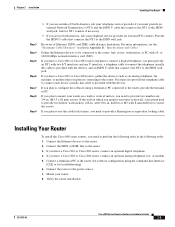
... or vertical surface, you plan to configure the software using the command-line interface [CLI] or for troubleshooting). 6. Chapter 2 Installation Installing Your Router Step 3 Step 4 Step 5 Step 6 Step 7 Step 8 Step 9 • If you are in North America, ask your telephone service provider for external NT1 vendors. Connect the Ethernet devices to the router: hub, server, workstation, or PC with two S/T interfaces and one U interface, a telephone cable to connect the telephone (usually this cable is drywall, you instead need to...
... or vertical surface, you plan to configure the software using the command-line interface [CLI] or for troubleshooting). 6. Chapter 2 Installation Installing Your Router Step 3 Step 4 Step 5 Step 6 Step 7 Step 8 Step 9 • If you are in North America, ask your telephone service provider for external NT1 vendors. Connect the Ethernet devices to the router: hub, server, workstation, or PC with two S/T interfaces and one U interface, a telephone cable to connect the telephone (usually this cable is drywall, you instead need to...
Hardware Installation Guide
Page 29
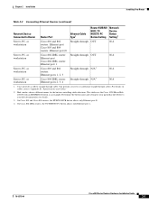
... routers, the HUB/NO HUB button affects only Ethernet port Ø. 4. Hub vendors choose different names for details. 3. On Cisco 804 IDSL routers, the TO HUB/TO PC button affects only Ethernet port 1. 78-5373-04 Cisco 800 Series Routers Hardware Installation Guide 2-7 This table uses the Cisco 1528 Micro Hub 10/100 with an MDI/MDI-X button as an example. Chapter 2 Installation Installing Your Router Table 2-2 Connecting Ethernet Devices (continued) Network Device Connected to Appendix B, "Specifications and Cables...
... routers, the HUB/NO HUB button affects only Ethernet port Ø. 4. Hub vendors choose different names for details. 3. On Cisco 804 IDSL routers, the TO HUB/TO PC button affects only Ethernet port 1. 78-5373-04 Cisco 800 Series Routers Hardware Installation Guide 2-7 This table uses the Cisco 1528 Micro Hub 10/100 with an MDI/MDI-X button as an example. Chapter 2 Installation Installing Your Router Table 2-2 Connecting Ethernet Devices (continued) Network Device Connected to Appendix B, "Specifications and Cables...
Hardware Installation Guide
Page 30
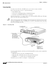
... the hub, set the HUB/NO HUB button or its equivalent. Follow the steps in Chapter 3, "Troubleshooting." Cisco 800 Series Routers Hardware Installation Guide 2-8 78-5373-04 Set HUB/NO HUB or TO HUB/TO PC button. Caution Always connect the yellow cable or an Ethernet cable to hub. 4. This figure shows a Cisco 803 router with four Ethernet ports. Before connecting a hub, see Table 3-2 in Figure 2-1 to connect a hub to...
... the hub, set the HUB/NO HUB button or its equivalent. Follow the steps in Chapter 3, "Troubleshooting." Cisco 800 Series Routers Hardware Installation Guide 2-8 78-5373-04 Set HUB/NO HUB or TO HUB/TO PC button. Caution Always connect the yellow cable or an Ethernet cable to hub. 4. This figure shows a Cisco 803 router with four Ethernet ports. Before connecting a hub, see Table 3-2 in Figure 2-1 to connect a hub to...
Hardware Installation Guide
Page 32
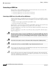
... card in the area of the ISDN port (RJ-45 connector), regardless of when power is turned to a Cisco 801 or Cisco 803 router with other devices. 2-10 Cisco 800 Series Routers Hardware Installation Guide 78-5373-04 Network hazardous voltages also are present in Figure 2-3 on the router. Do not connect the cable to the ISDN wall jack. To connect an ISDN line to standby. Warning Do not work...
... card in the area of the ISDN port (RJ-45 connector), regardless of when power is turned to a Cisco 801 or Cisco 803 router with other devices. 2-10 Cisco 800 Series Routers Hardware Installation Guide 78-5373-04 Network hazardous voltages also are present in Figure 2-3 on the router. Do not connect the cable to the ISDN wall jack. To connect an ISDN line to standby. Warning Do not work...
Hardware Installation Guide
Page 38
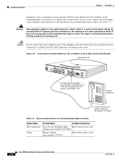
....rswww.com/ Adapter (part number 303-2000) Export Adapter (part number 2797057) http://www.tandy.co.uk/ 2-16 Cisco 800 Series Routers Hardware Installation Guide 78-5373-04 Warning This equipment contains a ring signal generator (ringer), which causes incoming calls to work properly with the router phone ports. This connection can damage your router. Installing Your Router Chapter 2 Installation telephones, faxes, or modems to ring the connected devices. If you must...
....rswww.com/ Adapter (part number 303-2000) Export Adapter (part number 2797057) http://www.tandy.co.uk/ 2-16 Cisco 800 Series Routers Hardware Installation Guide 78-5373-04 Warning This equipment contains a ring signal generator (ringer), which causes incoming calls to work properly with the router phone ports. This connection can damage your router. Installing Your Router Chapter 2 Installation telephones, faxes, or modems to ring the connected devices. If you must...
Hardware Installation Guide
Page 41
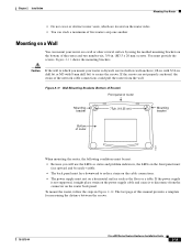
... of the network cable connections could pull the router from the connector on the bottom of this manual provides a template for measuring the distance between the screws. 78-5373-04 Cisco 800 Series Routers Hardware Installation Guide 2-19 If the power supply is not supported, it might place strain on the router sides. • You can mount your router is drywall, use the LEDs as the floor...
... of the network cable connections could pull the router from the connector on the bottom of this manual provides a template for measuring the distance between the screws. 78-5373-04 Cisco 800 Series Routers Hardware Installation Guide 2-19 If the power supply is not supported, it might place strain on the router sides. • You can mount your router is drywall, use the LEDs as the floor...
Hardware Installation Guide
Page 42
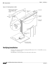
... power supply on screws. 3. Verifying Installation Verify the cable connections (links) by checking the LEDs listed in . (0.32 cm) Screw Maximum distance 6 ft (18 m) 11672 Chapter 2 Installation Front panel Mounting brackets 2. If the LEDs are not on Wall 1. Verifying Installation Figure 2-12 Mounting Router on , see Chapter 3, "Troubleshooting." The LINK LED is on the back panel of Cisco 801 and Cisco 802 routers. 2-20 Cisco 800 Series Routers Hardware Installation Guide 78-5373-04 Secure...
... power supply on screws. 3. Verifying Installation Verify the cable connections (links) by checking the LEDs listed in . (0.32 cm) Screw Maximum distance 6 ft (18 m) 11672 Chapter 2 Installation Front panel Mounting brackets 2. If the LEDs are not on Wall 1. Verifying Installation Figure 2-12 Mounting Router on , see Chapter 3, "Troubleshooting." The LINK LED is on the back panel of Cisco 801 and Cisco 802 routers. 2-20 Cisco 800 Series Routers Hardware Installation Guide 78-5373-04 Secure...

Hardware Installation Guide
Page 47
... link to an Ethernet device. (On Cisco 801, Cisco 802, and 802 IDSL routers, the LINK LED on server, PC, or workstation. • Run the NIC diagnostic supplied by the vendor to make sure you must provide an NT1 and the ISDN U cable. Check the cable information in Table 2-2 in Chapter 2, "Installation." • Check specifications in Table B-13 and Table B-14 in Chapter 2, "Installation." 78-5373-04 Cisco 800 Series Routers Hardware Installation Guide 3-3 Chapter 3 Troubleshooting Problems...
... link to an Ethernet device. (On Cisco 801, Cisco 802, and 802 IDSL routers, the LINK LED on server, PC, or workstation. • Run the NIC diagnostic supplied by the vendor to make sure you must provide an NT1 and the ISDN U cable. Check the cable information in Table 2-2 in Chapter 2, "Installation." • Check specifications in Table B-13 and Table B-14 in Chapter 2, "Installation." 78-5373-04 Cisco 800 Series Routers Hardware Installation Guide 3-3 Chapter 3 Troubleshooting Problems...
Hardware Installation Guide
Page 60
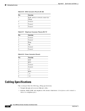
... 8 Unused Table B-11 Telephone Connector Pinouts (RJ-11) Pin Function 1 Unused 2 Unused 3 Ring 4 Tip 5 Unused 6 Unused Table B-12 Power Connector Pinouts Pin Function 1 ROF 2 RTN 3 Unused 4 Unused 5 +5 6 RTN 7 -71 8 -24 Cabling Specifications This section provides the following cabling specifications: • Straight-through and crossover Ethernet cables. • Ethernet, ISDN, IDSL and telephone cable distance limitations. (A telephone cable connects a device to a telephone port.) Cisco 800 Series Routers Hardware Installation Guide B-6 78-5373...
... 8 Unused Table B-11 Telephone Connector Pinouts (RJ-11) Pin Function 1 Unused 2 Unused 3 Ring 4 Tip 5 Unused 6 Unused Table B-12 Power Connector Pinouts Pin Function 1 ROF 2 RTN 3 Unused 4 Unused 5 +5 6 RTN 7 -71 8 -24 Cabling Specifications This section provides the following cabling specifications: • Straight-through and crossover Ethernet cables. • Ethernet, ISDN, IDSL and telephone cable distance limitations. (A telephone cable connects a device to a telephone port.) Cisco 800 Series Routers Hardware Installation Guide B-6 78-5373...
Hardware Installation Guide
Page 63
... Routers Hardware Installation Guide GL-1 B BRI Basic Rate Interface. crossover Ethernet cable A cable that wires a pin to TX+. for example, RX+ is wired to its opposite pin; GLOSSARY Numerics 10BASE-T The 10-Mbps baseband Ethernet specification that uses two pairs of twisted-pair cabling (Category 3 or 5): one data channel (D channel) for basic configurations and verification of the router software configuration. This cable connects two similar devices, for receiving data. C Cisco 800 Fast Step Application A Windows 95-, Windows...
... Routers Hardware Installation Guide GL-1 B BRI Basic Rate Interface. crossover Ethernet cable A cable that wires a pin to TX+. for example, RX+ is wired to its opposite pin; GLOSSARY Numerics 10BASE-T The 10-Mbps baseband Ethernet specification that uses two pairs of twisted-pair cabling (Category 3 or 5): one data channel (D channel) for basic configurations and verification of the router software configuration. This cable connects two similar devices, for receiving data. C Cisco 800 Fast Step Application A Windows 95-, Windows...

Hardware Installation Guide
Page 69
...to 2-7 troubleshooting 3-1 unpacking the router 2-4, ?? Index S S/T interface A-1 safety warnings 2-2 server, connecting 2-9 settings, network devices 2-6 to 2-7 specifications cabling B-6 system B-1 startup problems 3-2 T table mounting 2-18 telephone connecting 2-14, 2-15 ports described 1-2 illustrated 1-5, 1-6 temperature specifications B-1 terminal, connecting 2-17 TO HUB/TO PC button illustrated 1-6 to 1-7 settings 2-6 to 2-20 warnings, installation 2-2 weight specifications B-1 workstation, connecting 2-9 U U interface A-1 United Kingdom master sockets 2-16 78-5373-04 Cisco 800...
...to 2-7 troubleshooting 3-1 unpacking the router 2-4, ?? Index S S/T interface A-1 safety warnings 2-2 server, connecting 2-9 settings, network devices 2-6 to 2-7 specifications cabling B-6 system B-1 startup problems 3-2 T table mounting 2-18 telephone connecting 2-14, 2-15 ports described 1-2 illustrated 1-5, 1-6 temperature specifications B-1 terminal, connecting 2-17 TO HUB/TO PC button illustrated 1-6 to 1-7 settings 2-6 to 2-20 warnings, installation 2-2 weight specifications B-1 workstation, connecting 2-9 U U interface A-1 United Kingdom master sockets 2-16 78-5373-04 Cisco 800...

