Installation Guide
Page 1
... to radio or television communications at your Cisco 5500 Series Wireless Controller. • Compliance and Safety Information, page 1 • Controller Overview, page 3 • Unpacking and Installing the Controller, page 8 • Using the Startup Wizard, page 24 • Controller Specifications, page 31 • Obtaining Documentation and Submitting a Service Request, page 31 • Cisco 90-Day Limited Hardware Warranty Terms, page 31 Compliance and Safety...
... to radio or television communications at your Cisco 5500 Series Wireless Controller. • Compliance and Safety Information, page 1 • Controller Overview, page 3 • Unpacking and Installing the Controller, page 8 • Using the Startup Wizard, page 24 • Controller Specifications, page 31 • Obtaining Documentation and Submitting a Service Request, page 31 • Cisco 90-Day Limited Hardware Warranty Terms, page 31 Compliance and Safety...
Installation Guide
Page 2
... a rack or enclosed space. • When multiple Cisco 5500 Series Wireless Controllers are provided in procedures that may cause harmful interference to radio communications. Use the statement number provided at their own expense. Never defeat the ground conductor or operate the equipment in a situation that could cause bodily injury. Statement 1024 Statement 371-Power Cable and AC Adapter Cisco 5500 Series Wireless Controller Installation Guide...
... a rack or enclosed space. • When multiple Cisco 5500 Series Wireless Controllers are provided in procedures that may cause harmful interference to radio communications. Use the statement number provided at their own expense. Never defeat the ground conductor or operate the equipment in a situation that could cause bodily injury. Statement 1024 Statement 371-Power Cable and AC Adapter Cisco 5500 Series Wireless Controller Installation Guide...
Installation Guide
Page 3
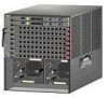
... The Cisco 5500 Series Wireless Controller is currently available in order to 250 lightweight access points and 7000 clients, making it is used in conjunction with a robust wireless LAN solution. If this guide, you should have any access points on the network, it ideal for 802.11n performance and maximum scalability, supports up to install and configure a controller. Because the radio resource management...
... The Cisco 5500 Series Wireless Controller is currently available in order to 250 lightweight access points and 7000 clients, making it is used in conjunction with a robust wireless LAN solution. If this guide, you should have any access points on the network, it ideal for 802.11n performance and maximum scalability, supports up to install and configure a controller. Because the radio resource management...
Installation Guide
Page 4
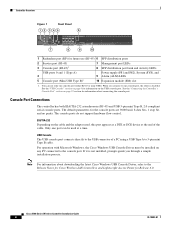
... the "USB Console" section on any PC connected to the USB connector of the cable. USB Console The USB console port connects directly to the console port. The console ports do not support hardware flow control. Only one port can use (RJ-45) 6 SFP distribution ports 2 Service port (RJ-45) 3 Console port (RJ-45)1 7 Management port LEDs 8 SFP distribution port Link and Activity LEDs USB ports 0 and 1 (Type A) 4 5 Console port (Mini USB Type B)1 Power supply (PS1 and PS2), System (SYS), and 9 Alarm (ALM) LEDs 10 Expansion module (EM) slot 1. You can be installed on page...
... the "USB Console" section on any PC connected to the USB connector of the cable. USB Console The USB console port connects directly to the console port. The console ports do not support hardware flow control. Only one port can use (RJ-45) 6 SFP distribution ports 2 Service port (RJ-45) 3 Console port (RJ-45)1 7 Management port LEDs 8 SFP distribution port Link and Activity LEDs USB ports 0 and 1 (Type A) 4 5 Console port (Mini USB Type B)1 Power supply (PS1 and PS2), System (SYS), and 9 Alarm (ALM) LEDs 10 Expansion module (EM) slot 1. You can be installed on page...

Installation Guide
Page 5
... the USB cable is removed from the console port without affecting Windows HyperTerminal operations. Only the 5-pin mini Type B can be used. Figure 2 12 Back Panel 251198 3 4 1 Power supply PS1 2 Power supply PS1 on/off switch 3 Power supply PS1 AC cable connection 5 4 Power supply PS2 slot with a power supply, a blank power supply cover, and a fan tray. Note An amber LED could indicate an error or a possible hardware failure. 78-18998-01 Cisco 5500 Series Wireless Controller Installation Guide 5 When a cable is not working properly, check the LEDs...
... the USB cable is removed from the console port without affecting Windows HyperTerminal operations. Only the 5-pin mini Type B can be used. Figure 2 12 Back Panel 251198 3 4 1 Power supply PS1 2 Power supply PS1 on/off switch 3 Power supply PS1 AC cable connection 5 4 Power supply PS2 slot with a power supply, a blank power supply cover, and a fan tray. Note An amber LED could indicate an error or a possible hardware failure. 78-18998-01 Cisco 5500 Series Wireless Controller Installation Guide 5 When a cable is not working properly, check the LEDs...
Installation Guide
Page 6
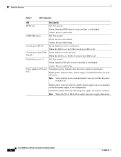
... LED is established. Amber: Present with failure. Green: Indicates SFP port is active and link is amber, the power supply shuts down. Amber: Present with failure. Blinks green: Indicates that the power switch is off . Controller Overview Table 1 LED Indicators LED RP/SP port USB0/USB1 port Console port (RJ-45) Console port (mini-USB Type B) Distribution ports 1-8 Power supplies (PS1 and PS2) Description Off: Not present. When this LED is on , the USB console port LED is off . Cisco 5500 Series Wireless Controller Installation Guide 6 78-18998-01 Green...
... LED is established. Amber: Present with failure. Green: Indicates SFP port is active and link is amber, the power supply shuts down. Amber: Present with failure. Blinks green: Indicates that the power switch is off . Controller Overview Table 1 LED Indicators LED RP/SP port USB0/USB1 port Console port (RJ-45) Console port (mini-USB Type B) Distribution ports 1-8 Power supplies (PS1 and PS2) Description Off: Not present. When this LED is on , the USB console port LED is off . Cisco 5500 Series Wireless Controller Installation Guide 6 78-18998-01 Green...
Installation Guide
Page 8
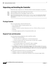
... securing the mounting hardware • #1 Phillips screwdriver for downloading operating system software updates). Network, operating system service network, and access point cables as the Cisco WCS because Cisco WCS and third-party TFTP servers use the same communication port. Null modem serial cable to the shipping container and save it for damage. Return all items listed in the "Package Contents" section on the same workstation as required • Command-line interface (CLI) console - If any...
... securing the mounting hardware • #1 Phillips screwdriver for downloading operating system software updates). Network, operating system service network, and access point cables as the Cisco WCS because Cisco WCS and third-party TFTP servers use the same communication port. Null modem serial cable to the shipping container and save it for damage. Return all items listed in the "Package Contents" section on the same workstation as required • Command-line interface (CLI) console - If any...
Installation Guide
Page 9
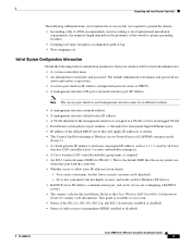
... management interface must be hijacked). - The default administrative username and password are required to ground the chassis: • Grounding cable (6 AWG recommended), sized according to allow static IP addresses from your wireless LAN or network administrator: • A system (controller) name. • An administrative username and password. Refer to accommodate girth of radio resource management (RRM) (enabled or disabled). 78-18998-01 Cisco 5500 Series Wireless Controller Installation Guide 9 No is available at cisco.com. • Status...
... management interface must be hijacked). - The default administrative username and password are required to ground the chassis: • Grounding cable (6 AWG recommended), sized according to allow static IP addresses from your wireless LAN or network administrator: • A system (controller) name. • An administrative username and password. Refer to accommodate girth of radio resource management (RRM) (enabled or disabled). 78-18998-01 Cisco 5500 Series Wireless Controller Installation Guide 9 No is available at cisco.com. • Status...
Installation Guide
Page 10
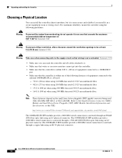
... Pluggable (SFP) GBIC Module Installation Information and Specifications, at least: 4 in an area that wiring is within one of the following guidelines: Warning To prevent the system from overheating, do not operate it in (10.16 cm) Statement 1076 Warning Take care when connecting units to a network through a copper link using an LC physical connector. Cisco 5500 Series Wireless Controller Installation Guide 10...
... Pluggable (SFP) GBIC Module Installation Information and Specifications, at least: 4 in an area that wiring is within one of the following guidelines: Warning To prevent the system from overheating, do not operate it in (10.16 cm) Statement 1076 Warning Take care when connecting units to a network through a copper link using an LC physical connector. Cisco 5500 Series Wireless Controller Installation Guide 10...

Installation Guide
Page 16
... flush mount the controller in a 2-post equipment rack: Step 1 Attach one power supply connection. Note Only three of the front brackets to the controller using three M4 screws (see Figure 11). Warning This unit might have more people must be removed to de-energize the unit. Cisco 5500 Series Wireless Controller Installation Guide 16 78-18998-01 All connections must work together to install the controller. Unpacking and Installing the Controller...
... flush mount the controller in a 2-post equipment rack: Step 1 Attach one power supply connection. Note Only three of the front brackets to the controller using three M4 screws (see Figure 11). Warning This unit might have more people must be removed to de-energize the unit. Cisco 5500 Series Wireless Controller Installation Guide 16 78-18998-01 All connections must work together to install the controller. Unpacking and Installing the Controller...

Installation Guide
Page 20
... We recommend grounding the chassis, even if the rack is provided on the chassis (such as the rear bracket mount holes using an M3 screw) using your own grounding lug. A grounding pad with two threaded M4 holes is already grounded. Caution All power supplies must always be made first and disconnected last. Cisco 5500 Series Wireless Controller Installation Guide 20 78-18998-01...
... We recommend grounding the chassis, even if the rack is provided on the chassis (such as the rear bracket mount holes using an M3 screw) using your own grounding lug. A grounding pad with two threaded M4 holes is already grounded. Caution All power supplies must always be made first and disconnected last. Cisco 5500 Series Wireless Controller Installation Guide 20 78-18998-01...
Installation Guide
Page 22
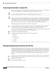
... controller's USB console port and the other end of the cable into the PC's USB Type A port. you use the RJ-45 console port, plug the RJ-45 connector on the CLI screen. Follow these steps to the COM port. Follow these steps to connect the PC to the controller's console port: Step 1 Step 2 Step 3 If you then need to connect it to a PC that you connect a Windows PC to install the driver...
... controller's USB console port and the other end of the cable into the PC's USB Type A port. you use the RJ-45 console port, plug the RJ-45 connector on the CLI screen. Follow these steps to the COM port. Follow these steps to connect the PC to the controller's console port: Step 1 Step 2 Step 3 If you then need to connect it to a PC that you connect a Windows PC to install the driver...

Installation Guide
Page 23
... not reboot the controller until the user login prompt appears. All rights reserved. Format FLASH Drive 6. Starting SSHPM LSC PROV LIST: ok Starting Management Services: Web Server: ok CLI: ok Secure Web: ok License Agent: ok 78-18998-01 Cisco 5500 Series Wireless Controller Installation Guide 23 Unpacking and Installing the Controller The bootup script displays operating system software initialization (code download and POST verification) and basic configuration as shown in FIPS mode. OK. . . . Boot...
... not reboot the controller until the user login prompt appears. All rights reserved. Format FLASH Drive 6. Starting SSHPM LSC PROV LIST: ok Starting Management Services: Web Server: ok CLI: ok Secure Web: ok License Agent: ok 78-18998-01 Cisco 5500 Series Wireless Controller Installation Guide 23 Unpacking and Installing the Controller The bootup script displays operating system software initialization (code download and POST verification) and basic configuration as shown in FIPS mode. OK. . . . Boot...

Installation Guide
Page 24
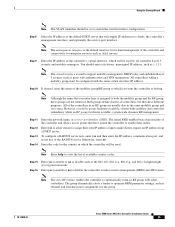
... downloads a configuration file from a TFTP server and then loads the configuration onto the controller automatically. If you do not enter yes, the AutoInstall process begins after each . Note The service-port interface controls communications through a dedicated management network to 24 ASCII characters for each configuration parameter. Enable or disable link aggregation (LAG) by choosing yes or no. You can enter up to ensure service access during network downtime. Enter the administrative username and password...
... downloads a configuration file from a TFTP server and then loads the configuration onto the controller automatically. If you do not enter yes, the AutoInstall process begins after each . Note The service-port interface controls communications through a dedicated management network to 24 ASCII characters for each configuration parameter. Enable or disable link aggregation (LAG) by choosing yes or no. You can enter up to ensure service access during network downtime. Enter the administrative username and password...
Installation Guide
Page 25
...) auto RF feature. You should be used by all controller Layer 3 security and mobility managers. Note The management interface is used to optimize RRM parameter settings, such as AAA servers. Step 10 If desired, enter the name of controllers, but they have joined the controller to enterprise services such as channel and transmit power assignment, for the group. 78-18998-01 Cisco 5500 Series Wireless Controller Installation Guide 25 To configure a RADIUS server...
...) auto RF feature. You should be used by all controller Layer 3 security and mobility managers. Note The management interface is used to optimize RRM parameter settings, such as AAA servers. Step 10 If desired, enter the name of controllers, but they have joined the controller to enterprise services such as channel and transmit power assignment, for the group. 78-18998-01 Cisco 5500 Series Wireless Controller Installation Guide 25 To configure a RADIUS server...
Installation Guide
Page 26
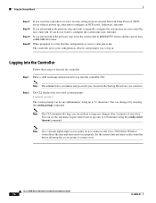
... format and the current time in . Note The administrative username and password you created in the previous step and want the controller to receive its time setting from 0 (never log out) to 160 minutes using the config serial timeout command. Note The CLI automatically logs you do not connect to the Cisco 5500 Series Wireless Controller if the date and time are case sensitive. Cisco 5500 Series Wireless Controller Installation Guide 26 78-18998...
... format and the current time in . Note The administrative username and password you created in the previous step and want the controller to receive its time setting from 0 (never log out) to 160 minutes using the config serial timeout command. Note The CLI automatically logs you do not connect to the Cisco 5500 Series Wireless Controller if the date and time are case sensitive. Cisco 5500 Series Wireless Controller Installation Guide 26 78-18998...
Installation Guide
Page 27
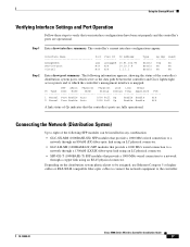
... controller's current interface configurations appear: Step 2 Interface Name management service-port virtual Port ---LAG N/A N/A Vlan Id -------untagged N/A N/A IP Address 10.91.104.93 10.10.0.9 1.1.1.1 Type ------Static Static Static Ap Mgr Guest Yes No No No No No Enter show interface summary. The following SFP modules can be assigned, use Ethernet Category 5 or higher cables or SX/LX/LH compatible fiber-optic cables to connect the network equipment to the controller. 78-18998-01 Cisco 5500 Series Wireless Controller Installation Guide...
... controller's current interface configurations appear: Step 2 Interface Name management service-port virtual Port ---LAG N/A N/A Vlan Id -------untagged N/A N/A IP Address 10.91.104.93 10.10.0.9 1.1.1.1 Type ------Static Static Static Ap Mgr Guest Yes No No No No No Enter show interface summary. The following SFP modules can be assigned, use Ethernet Category 5 or higher cables or SX/LX/LH compatible fiber-optic cables to connect the network equipment to the controller. 78-18998-01 Cisco 5500 Series Wireless Controller Installation Guide...
Installation Guide
Page 28
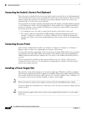
... configured the controller, use Category-5, Category-5e, Category-6, or Category-7 Ethernet cables to connect Cisco lightweight access points to remove power from a PC running a terminal emulation program or a PC running Cisco WCS, a network management tool that enables you must switch off and unplug the power supply. Refer to replace a power supply. When the controller is equipped with two power supply units, the power supplies are hot swappable; Also, the power supplies are redundant. One power supply unit is optional. Cisco 5500 Series Wireless Controller Installation Guide...
... configured the controller, use Category-5, Category-5e, Category-6, or Category-7 Ethernet cables to connect Cisco lightweight access points to remove power from a PC running a terminal emulation program or a PC running Cisco WCS, a network management tool that enables you must switch off and unplug the power supply. Refer to replace a power supply. When the controller is equipped with two power supply units, the power supplies are hot swappable; Also, the power supplies are redundant. One power supply unit is optional. Cisco 5500 Series Wireless Controller Installation Guide...
Installation Guide
Page 31
... applicable to read the Cisco Information Packet, follow these steps to access and download the Cisco Information Packet and your browser, and go to Cisco software, is highlighted. To read the document. b. Cisco 90-Day Limited Hardware Warranty Terms There are a free service and Cisco currently supports RSS Version 2.0. Select the language in which also lists all new and revised Cisco technical documentation, at: http://www.cisco.com/en/US/docs...
... applicable to read the Cisco Information Packet, follow these steps to access and download the Cisco Information Packet and your browser, and go to Cisco software, is highlighted. To read the document. b. Cisco 90-Day Limited Hardware Warranty Terms There are a free service and Cisco currently supports RSS Version 2.0. Select the language in which also lists all new and revised Cisco technical documentation, at: http://www.cisco.com/en/US/docs...
Installation Guide
Page 32
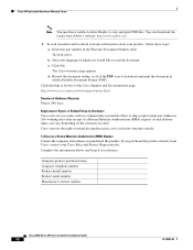
... Acrobat Reader to ship a replacement part within ten (10) working days after receipt of Hardware Warranty Ninety (90) days. d. Complete the information below, and keep it for Hardware Cisco or its exclusive warranty remedy. c. Actual delivery times can download the reader from Company telephone number Product model number Product serial number Maintenance contract number Cisco 5500 Series Wireless Controller Installation Guide 32 78-18998-01 Cisco reserves the right to...
... Acrobat Reader to ship a replacement part within ten (10) working days after receipt of Hardware Warranty Ninety (90) days. d. Complete the information below, and keep it for Hardware Cisco or its exclusive warranty remedy. c. Actual delivery times can download the reader from Company telephone number Product model number Product serial number Maintenance contract number Cisco 5500 Series Wireless Controller Installation Guide 32 78-18998-01 Cisco reserves the right to...

