Installation Guide
Page 10
... your software release: • Catalyst 4500 Series Switch Cisco IOS Software Configuration Guide http://www.cisco.com/en/US/products/hw/switches/ps4324/products_installation_and_configurati on_guides_list.html • Catalyst 4500 Series Switch Cisco IOS Command Reference http://www.cisco.com/en/US/products/hw/switches/ps4324/prod_command_reference_list.html • Catalyst 4500 Series Switch Cisco IOS System Message Guide http://www.cisco.com/en/US/products/hw...
... your software release: • Catalyst 4500 Series Switch Cisco IOS Software Configuration Guide http://www.cisco.com/en/US/products/hw/switches/ps4324/products_installation_and_configurati on_guides_list.html • Catalyst 4500 Series Switch Cisco IOS Command Reference http://www.cisco.com/en/US/products/hw/switches/ps4324/prod_command_reference_list.html • Catalyst 4500 Series Switch Cisco IOS System Message Guide http://www.cisco.com/en/US/products/hw...
Installation Guide
Page 17
... features identified. Tip For additional information about the Cisco Catalyst 4948E and the Catalyst 4948E-F switches (including configuration examples and troubleshooting information), see the documents listed on this page: http://www.cisco.com/en/US/products/ps6021/tsd_products_support_series_home.html OL-21561-02 Catalyst 4948E and Catalyst 4948E-F Switch Installation Guide 1-1 Both switches have one removable fan tray and support redundant...
... features identified. Tip For additional information about the Cisco Catalyst 4948E and the Catalyst 4948E-F switches (including configuration examples and troubleshooting information), see the documents listed on this page: http://www.cisco.com/en/US/products/ps6021/tsd_products_support_series_home.html OL-21561-02 Catalyst 4948E and Catalyst 4948E-F Switch Installation Guide 1-1 Both switches have one removable fan tray and support redundant...
Installation Guide
Page 20
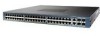
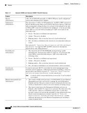
... amber-The system has detected a fault with RJ-45 connectors at each end. Features Chapter 1 Product Overview Table 1-1 Catalyst 4948E and Catalyst 4948E-F Switch Features Feature Chassis (both chassis) Uplink ports (both chassis) Downlink ports (both chassis) Console port (both chassis) Ethernet... management port (both chassis) Description 1-RU, 48 10/100/1000 ports plus 4 1-GB/10-GB ports, fixed configuration switch with ...
... amber-The system has detected a fault with RJ-45 connectors at each end. Features Chapter 1 Product Overview Table 1-1 Catalyst 4948E and Catalyst 4948E-F Switch Features Feature Chassis (both chassis) Uplink ports (both chassis) Downlink ports (both chassis) Console port (both chassis) Ethernet... management port (both chassis) Description 1-RU, 48 10/100/1000 ports plus 4 1-GB/10-GB ports, fixed configuration switch with ...
Installation Guide
Page 29
...1030 Warning This unit is essential for successful system operation. Statement 1017 OL-21561-02 Catalyst 4948E and Catalyst 4948E-F Switch Installation Guide 2-1 A warning symbol precedes each warning statement. The warnings below are applicable...Preparation Checklist, page 2-13 Tip For additional information about the Cisco Catalyst 4948E or the Catalyst 4948E-F switch (including configuration examples and troubleshooting information), see the documents listed on this page: http://www.cisco.com/en/US/products/ps6021/tsd_products_support_series_home.html Safety Safety warnings appear...
...1030 Warning This unit is essential for successful system operation. Statement 1017 OL-21561-02 Catalyst 4948E and Catalyst 4948E-F Switch Installation Guide 2-1 A warning symbol precedes each warning statement. The warnings below are applicable...Preparation Checklist, page 2-13 Tip For additional information about the Cisco Catalyst 4948E or the Catalyst 4948E-F switch (including configuration examples and troubleshooting information), see the documents listed on this page: http://www.cisco.com/en/US/products/ps6021/tsd_products_support_series_home.html Safety Safety warnings appear...
Installation Guide
Page 39
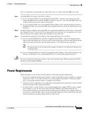
...in the external wiring or a tripped circuit breaker. • To prevent a loss of the antistatic strap. OL-21561-02 Catalyst 4948E and Catalyst 4948E-F Switch Installation Guide 2-11 We recommend that you touch the clip to an unpainted rack rail so that any built-up static charge ...clip jaws open wide enough to protect against power failures at your bare skin. Chapter 2 Preparing for the switch installation, follow these general requirements: • In systems configured with the FRUs, open the package and remove the ESD wrist strap. Locate the end of the lug screw...
...in the external wiring or a tripped circuit breaker. • To prevent a loss of the antistatic strap. OL-21561-02 Catalyst 4948E and Catalyst 4948E-F Switch Installation Guide 2-11 We recommend that you touch the clip to an unpainted rack rail so that any built-up static charge ...clip jaws open wide enough to protect against power failures at your bare skin. Chapter 2 Preparing for the switch installation, follow these general requirements: • In systems configured with the FRUs, open the package and remove the ESD wrist strap. Locate the end of the lug screw...
Installation Guide
Page 43
...: • Warnings, page 3-2 • Verifying Package Contents, page 3-4 • Required Tools, page 3-4 • Lifting the Chassis Safely, page 3-5 Tip For additional information about the Cisco Catalyst 4948E and the Catalyst 4948E-F switches (including configuration examples and troubleshooting information), see the documents listed on this chapter, complete the site planning checklist in this page: http://www...
...: • Warnings, page 3-2 • Verifying Package Contents, page 3-4 • Required Tools, page 3-4 • Lifting the Chassis Safely, page 3-5 Tip For additional information about the Cisco Catalyst 4948E and the Catalyst 4948E-F switches (including configuration examples and troubleshooting information), see the documents listed on this chapter, complete the site planning checklist in this page: http://www...

Installation Guide
Page 51
...-mount bracket using the single M4 screw provided. (See Figure 3-3.) Figure 3-3 Installing the Cable Guide 207511 Installing the Catalyst 4948E-F Switch Chassis with the kit. Chapter 3 Installing the Switch Rack-Mounting the Chassis To install the cable guide, follow these steps: Step 1 Step 2 Position the cable guide...rack-mount bracket. To install the air duct assembly, refer to the installation note that is configured as hot isle and cold isle, you are installing the Catalyst 4948E-F switch chassis in front of the equipment rack allowing the system to draw in cool air from the...
...-mount bracket using the single M4 screw provided. (See Figure 3-3.) Figure 3-3 Installing the Cable Guide 207511 Installing the Catalyst 4948E-F Switch Chassis with the kit. Chapter 3 Installing the Switch Rack-Mounting the Chassis To install the cable guide, follow these steps: Step 1 Step 2 Position the cable guide...rack-mount bracket. To install the air duct assembly, refer to the installation note that is configured as hot isle and cold isle, you are installing the Catalyst 4948E-F switch chassis in front of the equipment rack allowing the system to draw in cool air from the...
Installation Guide
Page 58
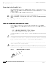
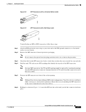
... wrist strap or similar individual grounding device when handling SFP transceivers. The ports configure themselves to operate at the other end of the network cable to a downlink port on the Catalyst 4948E support either 1000BASE-X SFP or 10GBASE SFP+ transceivers. If the attached .... Repeat Steps 1 and 2 for the remaining downlink ports. Figure 3-7 SFP Transceiver with a Mylar Tab Latch 63065 3-16 Catalyst 4948E and Catalyst 4948E-F Switch Installation Guide OL-21561-02 Do not remove and insert SFP transceivers more often than is absolutely necessary. Removing and installing an ...
... wrist strap or similar individual grounding device when handling SFP transceivers. The ports configure themselves to operate at the other end of the network cable to a downlink port on the Catalyst 4948E support either 1000BASE-X SFP or 10GBASE SFP+ transceivers. If the attached .... Repeat Steps 1 and 2 for the remaining downlink ports. Figure 3-7 SFP Transceiver with a Mylar Tab Latch 63065 3-16 Catalyst 4948E and Catalyst 4948E-F Switch Installation Guide OL-21561-02 Do not remove and insert SFP transceivers more often than is absolutely necessary. Removing and installing an ...
Installation Guide
Page 59
...transceiver body to do so later in front of the SFP transceiver. Your Cisco device could have different SFP socket configurations. OL-21561-02 Catalyst 4948E and Catalyst 4948E-F Switch Installation Guide 3-17 Note Different Cisco devices have either an SFP or SFP+ transceiver, follow these steps: ... dust plugs until you are installing the SFP transceiver in Figure 3-10, insert the SFP into place. Chapter 3 Installing the Switch Figure 3-8 SFP Transceiver with an Actuator Button Latch Attaching the Interface Cables 63066 Figure 3-9 SFP Transceiver with a Bail-Clasp Latch...
...transceiver body to do so later in front of the SFP transceiver. Your Cisco device could have different SFP socket configurations. OL-21561-02 Catalyst 4948E and Catalyst 4948E-F Switch Installation Guide 3-17 Note Different Cisco devices have either an SFP or SFP+ transceiver, follow these steps: ... dust plugs until you are installing the SFP transceiver in Figure 3-10, insert the SFP into place. Chapter 3 Installing the Switch Figure 3-8 SFP Transceiver with an Actuator Button Latch Attaching the Interface Cables 63066 Figure 3-9 SFP Transceiver with a Bail-Clasp Latch...
Installation Guide
Page 62
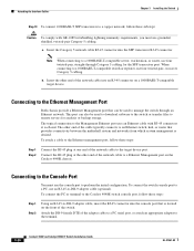
... crossover Category 5 cabling. This port can be used to a Ethernet Management port on the Catalyst 4948E chassis. The other end of the network cable to perform the initial configuration. To connect the switch console port to a PC, use an RJ-45-to the Management Ethernet port uses an ... a Ethernet Management port that is desired. To connect the PC or terminal to the Catalyst 4948E switch console port, follow these steps: Step 1 Step 2 Using an RJ-45-to the terminal. 3-20 Catalyst 4948E and Catalyst 4948E-F Switch Installation Guide OL-21561-02 Attach the DB-9 female DTE of the...
... crossover Category 5 cabling. This port can be used to a Ethernet Management port on the Catalyst 4948E chassis. The other end of the network cable to perform the initial configuration. To connect the switch console port to a PC, use an RJ-45-to the Management Ethernet port uses an ... a Ethernet Management port that is desired. To connect the PC or terminal to the Catalyst 4948E switch console port, follow these steps: Step 1 Step 2 Using an RJ-45-to the terminal. 3-20 Catalyst 4948E and Catalyst 4948E-F Switch Installation Guide OL-21561-02 Attach the DB-9 female DTE of the...

Installation Guide
Page 63
... Catalyst 4948E-F Switch Installation Guide 3-21 Chapter 3 Installing the Switch Powering Up the Switch Powering Up the Switch This section provides a quick power-up the chassis: Step 1 Step 2 Switch the power supply power switches to the ON position. The LEDs should be green when the power supply and the power supply fan are using a PC or terminal. Configure...
... Catalyst 4948E-F Switch Installation Guide 3-21 Chapter 3 Installing the Switch Powering Up the Switch Powering Up the Switch This section provides a quick power-up the chassis: Step 1 Step 2 Switch the power supply power switches to the ON position. The LEDs should be green when the power supply and the power supply fan are using a PC or terminal. Configure...

Installation Guide
Page 64
...DC-Input Power Supply (PWR-C49-300DC)" section on page A-12 for loops. For information on configuring the Catalyst 4948E or the Catalyst 4948E-F switch, refer to the appropriate software configuration guide at the INPUT OK and the OUTPUT OK LEDs located on the power supply faceplate. Note...or any tape from the source DC circuit breaker switch handle, and restore source DC power by looking at : http://www.cisco.com/en/US/products/ps6021/products_installation_and_configuration_guides_list.ht ml 3-22 Catalyst 4948E and Catalyst 4948E-F Switch Installation Guide OL-21561-02 The LEDs should be...
...DC-Input Power Supply (PWR-C49-300DC)" section on page A-12 for loops. For information on configuring the Catalyst 4948E or the Catalyst 4948E-F switch, refer to the appropriate software configuration guide at the INPUT OK and the OUTPUT OK LEDs located on the power supply faceplate. Note...or any tape from the source DC circuit breaker switch handle, and restore source DC power by looking at : http://www.cisco.com/en/US/products/ps6021/products_installation_and_configuration_guides_list.ht ml 3-22 Catalyst 4948E and Catalyst 4948E-F Switch Installation Guide OL-21561-02 The LEDs should be...

Installation Guide
Page 65
...-input-PWR-C49E-300AC-R DC-input-PWR-C49-300DC WS-X4994 Catalyst 4948E-F WS-X4993-F AC-input-PWR-C49E-300AC-F WS-X4994-F OL-21561-02 Catalyst 4948E and Catalyst 4948E-F Switch Installation Guide 4-1 Statement 1030 Tip For additional information about the Cisco Catalyst 4948E switch (including configuration examples and troubleshooting information), see the documents listed on this equipment...
...-input-PWR-C49E-300AC-R DC-input-PWR-C49-300DC WS-X4994 Catalyst 4948E-F WS-X4993-F AC-input-PWR-C49E-300AC-F WS-X4994-F OL-21561-02 Catalyst 4948E and Catalyst 4948E-F Switch Installation Guide 4-1 Statement 1030 Tip For additional information about the Cisco Catalyst 4948E switch (including configuration examples and troubleshooting information), see the documents listed on this equipment...
Installation Guide
Page 77
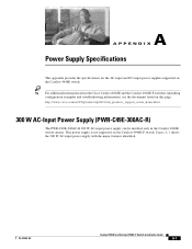
...-input power supply can be installed only in the Catalyst 4948E switch chassis. Tip For additional information about the Cisco Catalyst 4948E and the Catalyst 4948E-F switches (including configuration examples and troubleshooting information), see the documents listed on the Catalyst 4948E switch. This power supply is not supported on the Catalyst 4948E-F switch. Figure A-1 shows the 300 W AC-input power supply...
...-input power supply can be installed only in the Catalyst 4948E switch chassis. Tip For additional information about the Cisco Catalyst 4948E and the Catalyst 4948E-F switches (including configuration examples and troubleshooting information), see the documents listed on the Catalyst 4948E switch. This power supply is not supported on the Catalyst 4948E-F switch. Figure A-1 shows the 300 W AC-input power supply...

Installation Guide
Page 91
... • Ethernet Management Port, page B-12 • Cables and Adapters, page B-12 Tip For additional information about the Cisco Catalyst 4948E and the Catalyst 4948E-F switches (including configuration examples and troubleshooting information), see the documents listed on this page: http://www.cisco.com/en/US/products/ps6021/tsd_products_support_series_home.html Transceiver Support for Uplink Ports Both the...
... • Ethernet Management Port, page B-12 • Cables and Adapters, page B-12 Tip For additional information about the Cisco Catalyst 4948E and the Catalyst 4948E-F switches (including configuration examples and troubleshooting information), see the documents listed on this page: http://www.cisco.com/en/US/products/ps6021/tsd_products_support_series_home.html Transceiver Support for Uplink Ports Both the...

Installation Guide
Page 105
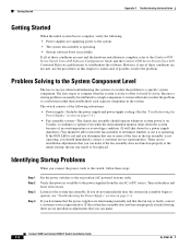
Tip For additional information about the Cisco Catalyst 4948E switch (including configuration examples and troubleshooting information), see the documents listed on this chapter to help isolate the cause. Although temperature conditions above the maximum acceptable level ... the Power Supply, page C-4 • Contacting Customer Service, page C-4 If your system has problems starting up, use the information in this page: http://www.cisco.com/en/US/products/ps6021/tsd_products_support_series_home.html OL-21561-02 Catalyst 4948E and Catalyst 4948E-F Switch Installation Guide C-1
Tip For additional information about the Cisco Catalyst 4948E switch (including configuration examples and troubleshooting information), see the documents listed on this chapter to help isolate the cause. Although temperature conditions above the maximum acceptable level ... the Power Supply, page C-4 • Contacting Customer Service, page C-4 If your system has problems starting up, use the information in this page: http://www.cisco.com/en/US/products/ps6021/tsd_products_support_series_home.html OL-21561-02 Catalyst 4948E and Catalyst 4948E-F Switch Installation Guide C-1
Installation Guide
Page 106
... fan assembly should be able to hear the fan assembly to determine whether or not it is complete, refer to the Catalyst 4500 Series Switch Cisco IOS Software Configuration Guide and the Catalyst 4500 Series Switch Cisco IOS Command Reference publications to troubleshoot the software. If the FAN LED is on position (AC powered systems only). Because...
... fan assembly should be able to hear the fan assembly to determine whether or not it is complete, refer to the Catalyst 4500 Series Switch Cisco IOS Software Configuration Guide and the Catalyst 4500 Series Switch Cisco IOS Command Reference publications to troubleshoot the software. If the FAN LED is on position (AC powered systems only). Because...

Installation Guide
Page 107
...8226; Green-DC input voltage is greater than -38.25 ±2.25 V. • Red-In a dual power supply configuration (alternate unit powered) the DC input is less than 33 ±3 V, or the power supply is turned off. • Off...ON. • Green-AC input voltage is greater than 82 ±3 V. • Red-In a dual power supply configuration (alternate unit powered) the AC input is less than 73 ±3 V, or the power supply is turned off. •... determine when and where the system failed in the startup sequence. OL-21561-02 Catalyst 4948E and Catalyst 4948E-F Switch Installation Guide C-3
...8226; Green-DC input voltage is greater than -38.25 ±2.25 V. • Red-In a dual power supply configuration (alternate unit powered) the DC input is less than 33 ±3 V, or the power supply is turned off. • Off...ON. • Green-AC input voltage is greater than 82 ±3 V. • Red-In a dual power supply configuration (alternate unit powered) the AC input is less than 73 ±3 V, or the power supply is turned off. •... determine when and where the system failed in the startup sequence. OL-21561-02 Catalyst 4948E and Catalyst 4948E-F Switch Installation Guide C-3

Installation Guide
Page 109
..., California Code of Regulations, Chapter 33), page D-43 • EMC Class A Notices and Warnings, page D-43 Tip For additional information about the Cisco Catalyst 4948E and the Catalyst 4948E-F switches (including configuration examples and troubleshooting information), see the documents listed on any equipment, be familiar with the U.S. You are in a situation that accompanied this page...
..., California Code of Regulations, Chapter 33), page D-43 • EMC Class A Notices and Warnings, page D-43 Tip For additional information about the Cisco Catalyst 4948E and the Catalyst 4948E-F switches (including configuration examples and troubleshooting information), see the documents listed on any equipment, be familiar with the U.S. You are in a situation that accompanied this page...
Installation Guide
Page 158
...ports 1-4 Ethernet management port 1-4 fan tray 1-5 fan tray LED 1-5 power supplies description 1-6 RESET switch 1-5 uplink port LEDs 1-4 uplink ports 1-4 Catalyst 4948E switches blank power supply cover 1-6 console port 1-4 downlink port LEDs 1-4 downlink ports 1-4 Ethernet management ...features 1-3 chassis features (front view) 1-2 chassis installation, tools required 3-4 checklist, site preparation 2-13 command conventions x configuration initial switch configuration 3-21 terminal-emulation software 3-21 console port connecting to 3-20 description 1-4, B-10 LED B-11 pinout table B-10 ...
...ports 1-4 Ethernet management port 1-4 fan tray 1-5 fan tray LED 1-5 power supplies description 1-6 RESET switch 1-5 uplink port LEDs 1-4 uplink ports 1-4 Catalyst 4948E switches blank power supply cover 1-6 console port 1-4 downlink port LEDs 1-4 downlink ports 1-4 Ethernet management ...features 1-3 chassis features (front view) 1-2 chassis installation, tools required 3-4 checklist, site preparation 2-13 command conventions x configuration initial switch configuration 3-21 terminal-emulation software 3-21 console port connecting to 3-20 description 1-4, B-10 LED B-11 pinout table B-10 ...


