
Installation Guide
Page 7
... N D I X C A P P E N D I X Management Port A-2 Catalyst 4900 Series Switch Specifications A-3 Initial Configuration for the Switch B-1 Connecting to the Switch B-2 Starting the Terminal-Emulation Software B-3 Connecting to a Power Source B-3 Entering the Initial Configuration Information B-4 IP Settings B-4 Performing the Initial Configuration B-5 Compliance Information and Translated Safety Warnings C-1 Translated Safety Warnings C-2 Statement 1003-DC Power ... Notice for Canada C-47 Statement 340-Class A Warning for CISPR22 C-47 78-18039-02 Catalyst 4900 Series Switch Installation Guide vii
... N D I X C A P P E N D I X Management Port A-2 Catalyst 4900 Series Switch Specifications A-3 Initial Configuration for the Switch B-1 Connecting to the Switch B-2 Starting the Terminal-Emulation Software B-3 Connecting to a Power Source B-3 Entering the Initial Configuration Information B-4 IP Settings B-4 Performing the Initial Configuration B-5 Compliance Information and Translated Safety Warnings C-1 Translated Safety Warnings C-2 Statement 1003-DC Power ... Notice for Canada C-47 Statement 340-Class A Warning for CISPR22 C-47 78-18039-02 Catalyst 4900 Series Switch Installation Guide vii
Installation Guide
Page 10
... for your software release: • Catalyst 4500 Series Switch Cisco IOS Software Configuration Guide http://www.cisco.com/en/US/products/hw/switches/ps4324/products_install ation_and_configuration_guides_list.html • Catalyst 4500 Series Switch Cisco IOS Command Reference http://www.cisco.com/en/US/products/hw/switches/ps4324/prod_command _reference_list.html • Catalyst 4500 Series Switch Cisco IOS System Message Guide http://www.cisco.com/en/US/products/hw...
... for your software release: • Catalyst 4500 Series Switch Cisco IOS Software Configuration Guide http://www.cisco.com/en/US/products/hw/switches/ps4324/products_install ation_and_configuration_guides_list.html • Catalyst 4500 Series Switch Cisco IOS Command Reference http://www.cisco.com/en/US/products/hw/switches/ps4324/prod_command _reference_list.html • Catalyst 4500 Series Switch Cisco IOS System Message Guide http://www.cisco.com/en/US/products/hw...
Installation Guide
Page 24
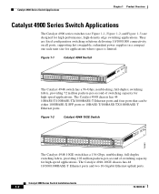
... 1-3) are fixed configuration switching solutions delivering 10/100/1000 connectivity on all ports, supporting hot swappable, redundant power supplies in a compact one rack-unit size for applications where space is limited. The Catalyst 4948-10GE chassis has 48 10/100/1000BASE-T Ethernet ports and two 10-Gigabit Ethernet uplink ports. Catalyst 4900 Series Switch Installation Guide 1-2 78-18039...
... 1-3) are fixed configuration switching solutions delivering 10/100/1000 connectivity on all ports, supporting hot swappable, redundant power supplies in a compact one rack-unit size for applications where space is limited. The Catalyst 4948-10GE chassis has 48 10/100/1000BASE-T Ethernet ports and two 10-Gigabit Ethernet uplink ports. Catalyst 4900 Series Switch Installation Guide 1-2 78-18039...
Installation Guide
Page 29
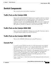
... and management ports. Traffic Ports on the Catalyst 4948-10GE There are 48 10/100/1000BASE-T Ethernet ports using RJ-45 interfaces and four 1000BASE-X Ethernet ports using standard console equipment. (See Figure 1-4.) A connector pinout table is supported on the switches. 78-18039-02 Catalyst 4900 Series Switch Installation Guide 1-7 These SFP ports share MAC addresses with...
... and management ports. Traffic Ports on the Catalyst 4948-10GE There are 48 10/100/1000BASE-T Ethernet ports using RJ-45 interfaces and four 1000BASE-X Ethernet ports using standard console equipment. (See Figure 1-4.) A connector pinout table is supported on the switches. 78-18039-02 Catalyst 4900 Series Switch Installation Guide 1-7 These SFP ports share MAC addresses with...
Installation Guide
Page 32
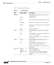
... 1-1 LED Functions LED STATUS Color or State Green Description At startup, the switch performs a series of diagnostic tests: All tests pass Red A test other ...a power supply has failed CON MGT Port 1-48 Off Green Off Green Off Green Yellow Flashing yellow Off Switch is disabled 10/100 BASE-T console port is in link-up state 10/100 BASE-T console port is ...-on self-test indicates faulty port No signal detected or link configuration failure 1-10 Catalyst 4900 Series Switch Installation Guide 78-18039-02 Switch Components Chapter 1 Product Overview Table 1-1 describes LED functions.
... 1-1 LED Functions LED STATUS Color or State Green Description At startup, the switch performs a series of diagnostic tests: All tests pass Red A test other ...a power supply has failed CON MGT Port 1-48 Off Green Off Green Off Green Yellow Flashing yellow Off Switch is disabled 10/100 BASE-T console port is in link-up state 10/100 BASE-T console port is ...-on self-test indicates faulty port No signal detected or link configuration failure 1-10 Catalyst 4900 Series Switch Installation Guide 78-18039-02 Switch Components Chapter 1 Product Overview Table 1-1 describes LED functions.
Installation Guide
Page 35
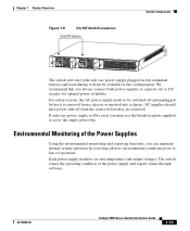
... supply plugged in this configuration. Each power supply monitors its own temperature and output voltages. We recommend that you can maintain normal system operation by resolving adverse environmental conditions prior to loss of the power supply and reports status through software. 78-18039-02 Catalyst 4900 Series Switch Installation Guide 1-13 Environmental Monitoring of...
... supply plugged in this configuration. Each power supply monitors its own temperature and output voltages. We recommend that you can maintain normal system operation by resolving adverse environmental conditions prior to loss of the power supply and reports status through software. 78-18039-02 Catalyst 4900 Series Switch Installation Guide 1-13 Environmental Monitoring of...

Installation Guide
Page 38
... Appendix A, "Specifications," lists the operating and nonoperating environmental site requirements for the switch. To ensure normal operation and avoid unnecessary maintenance, plan your site configuration and prepare your site. Keep the sides and rear clear of obstructions, including dust... Requirements, page 2-3 • Warnings and Cautions, page 2-3 Catalyst 4900 Series Switch Installation Guide 2-2 78-18039-02 Site Power Requirements This section describes the installation site power requirements for the switches. The environmental ranges listed in a rack with little or no...
... Appendix A, "Specifications," lists the operating and nonoperating environmental site requirements for the switch. To ensure normal operation and avoid unnecessary maintenance, plan your site configuration and prepare your site. Keep the sides and rear clear of obstructions, including dust... Requirements, page 2-3 • Warnings and Cautions, page 2-3 Catalyst 4900 Series Switch Installation Guide 2-2 78-18039-02 Site Power Requirements This section describes the installation site power requirements for the switches. The environmental ranges listed in a rack with little or no...
Installation Guide
Page 53
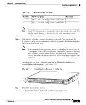
...when planning fastener points. Before installing the L brackets on the configuration of your rack. Chapter 3 Installing the Switch Rack-Mounting the Switch Table 3-1 Quantity 4 4 Rack-Mount Kit Checklist Part Description ... the chassis in the rack as follows (see Figure 3-3): 78-18039-02 Catalyst 4900 Series Switch Installation Guide 3-7 If the rack has this feature, consider the position of the rear ...See Figure 3-2.) Figure 3-2 Attaching the L Brackets to the Switch 130086 PS1 PS2 FAN STATUS 1 16 17 32 33 Catalyst WS-C4948 10GE X2-1 X2-2 CON 48 MGT Step 3 Install the ...
...when planning fastener points. Before installing the L brackets on the configuration of your rack. Chapter 3 Installing the Switch Rack-Mounting the Switch Table 3-1 Quantity 4 4 Rack-Mount Kit Checklist Part Description ... the chassis in the rack as follows (see Figure 3-3): 78-18039-02 Catalyst 4900 Series Switch Installation Guide 3-7 If the rack has this feature, consider the position of the rear ...See Figure 3-2.) Figure 3-2 Attaching the L Brackets to the Switch 130086 PS1 PS2 FAN STATUS 1 16 17 32 33 Catalyst WS-C4948 10GE X2-1 X2-2 CON 48 MGT Step 3 Install the ...
Installation Guide
Page 61
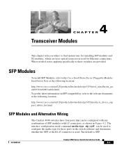
....cisco.com/en/US/products/hw/modules/ps5455/prod_installation_gu ide09186a00803aa0da.html To get the latest information on SFP compatibility, refer to configure the media type for these switches ... http://www.cisco.com/en/US/products/hw/modules/ps5455/products_device_sup port_tables_list.html SFP Modules and Alternative Wiring The Catalyst 4948 switches have four ports that can be configured with any ...combination of SFP modules with LC connectors, as shown in the switch software and determines ...
....cisco.com/en/US/products/hw/modules/ps5455/prod_installation_gu ide09186a00803aa0da.html To get the latest information on SFP compatibility, refer to configure the media type for these switches ... http://www.cisco.com/en/US/products/hw/modules/ps5455/products_device_sup port_tables_list.html SFP Modules and Alternative Wiring The Catalyst 4948 switches have four ports that can be configured with any ...combination of SFP modules with LC connectors, as shown in the switch software and determines ...

Installation Guide
Page 69
... often caused by poor or improper connections. Note For configuration questions or problems, refer to help isolate the cause. 5 C H A P T E R Troubleshooting the Installation This chapter describes how to troubleshoot the switch hardware installation and contains these sections: • Getting...system has problems starting up, use the information in this chapter to the software configuration guide or the command reference publication. 78-18039-02 Catalyst 4900 Series Switch Installation Guide 5-1 Problems with the initial startup are included because they also monitor DC-line voltages...
... often caused by poor or improper connections. Note For configuration questions or problems, refer to help isolate the cause. 5 C H A P T E R Troubleshooting the Installation This chapter describes how to troubleshoot the switch hardware installation and contains these sections: • Getting...system has problems starting up, use the information in this chapter to the software configuration guide or the command reference publication. 78-18039-02 Catalyst 4900 Series Switch Installation Guide 5-1 Problems with the initial startup are included because they also monitor DC-line voltages...

Installation Guide
Page 70
... is on page 5-5.) • Fan assembly system-The chassis fan assembly should immediately contact a customer service representative. The switch consists of an overtemperature or overvoltage condition. (It will shut down for a power supply shutdown.) You should be able ...assembly is operating. • System software boots successfully. Catalyst 4900 Series Switch Installation Guide 5-2 78-18039-02 If all of these conditions are met and the hardware installation is complete, refer to the Software Configuration Guide and the Command Reference publications to isolate and, if possible...
... is on page 5-5.) • Fan assembly system-The chassis fan assembly should immediately contact a customer service representative. The switch consists of an overtemperature or overvoltage condition. (It will shut down for a power supply shutdown.) You should be able ...assembly is operating. • System software boots successfully. Catalyst 4900 Series Switch Installation Guide 5-2 78-18039-02 If all of these conditions are met and the hardware installation is complete, refer to the Software Configuration Guide and the Command Reference publications to isolate and, if possible...
Installation Guide
Page 72
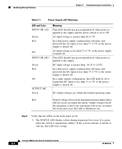
... not create an output fail alarm. DC input voltage is greater than 33 +/-3V, or the power supply is turned off . In a dual power supply configuration (alternate unit powered) the AC input is less than 33 +/-3V, or the power supply is turned off . Red Output voltage between the minimum and... OK (DC) Green Red Off OUTPUT OK Green Meaning This LED should turn green immediately when power is applied to the supply and the power switch is set to ON. Catalyst 4900 Series Switch Installation Guide 5-4 78-18039-02
... not create an output fail alarm. DC input voltage is greater than 33 +/-3V, or the power supply is turned off . In a dual power supply configuration (alternate unit powered) the AC input is less than 33 +/-3V, or the power supply is turned off . Red Output voltage between the minimum and... OK (DC) Green Red Off OUTPUT OK Green Meaning This LED should turn green immediately when power is applied to the supply and the power switch is set to ON. Catalyst 4900 Series Switch Installation Guide 5-4 78-18039-02

Installation Guide
Page 79
... B-2 2. These steps describe how to other Ethernet devices. 78-18039-02 Catalyst 4900 Series Switch Installation Guide B-1 Note You need to provide the Category 5 straight-through cables to connect the switch ports to do a simple installation: 1. Entering the Initial Configuration Information, page B-4 Note If you are using a DC power supply, see the "Connecting DC Power...
... B-2 2. These steps describe how to other Ethernet devices. 78-18039-02 Catalyst 4900 Series Switch Installation Guide B-1 Note You need to provide the Category 5 straight-through cables to connect the switch ports to do a simple installation: 1. Entering the Initial Configuration Information, page B-4 Note If you are using a DC power supply, see the "Connecting DC Power...
Installation Guide
Page 80
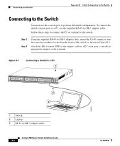
... 1 16 17 32 33 Catalyst 4948 CON 48 MGT 45 46 47 48 3 2 181874 1 Switch 2 Laptop 3 RJ-45-to-DB-9 adapter cable Catalyst 4900 Series Switch Installation Guide B-2 78-18039-02 Attach the DB-9 female DTE of the switch, as shown in Figure B-1. Connecting to the Switch Appendix B Initial Configuration for the Switch Connecting to the Switch You must use the...
... 1 16 17 32 33 Catalyst 4948 CON 48 MGT 45 46 47 48 3 2 181874 1 Switch 2 Laptop 3 RJ-45-to-DB-9 adapter cable Catalyst 4900 Series Switch Installation Guide B-2 78-18039-02 Attach the DB-9 female DTE of the switch, as shown in Figure B-1. Connecting to the Switch Appendix B Initial Configuration for the Switch Connecting to the Switch You must use the...
Installation Guide
Page 81
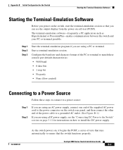
... output display from the power-on , it begins the POST, a series of tests that runs automatically to ensure that the switch functions properly. Configure the baud rate and character format of the PC or terminal to match these console port default characteristics: • 9600 baud... a grounded AC outlet. (See Figure B-1.) If you are using a PC or terminal. Appendix B Initial Configuration for instructions on how to install the DC power supply. 78-18039-02 As the switch powers on self-test (POST). Start a terminal-emulation session. Catalyst 4900 Series Switch Installation Guide B-3
... output display from the power-on , it begins the POST, a series of tests that runs automatically to ensure that the switch functions properly. Configure the baud rate and character format of the PC or terminal to match these console port default characteristics: • 9600 baud... a grounded AC outlet. (See Figure B-1.) If you are using a PC or terminal. Appendix B Initial Configuration for instructions on how to install the DC power supply. 78-18039-02 As the switch powers on self-test (POST). Start a terminal-emulation session. Catalyst 4900 Series Switch Installation Guide B-3
Installation Guide
Page 82
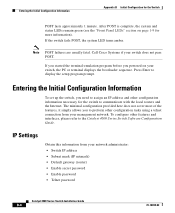
...Cisco Systems if your management network. Entering the Initial Configuration Information To set up the switch, you need to assign an IP address and other configuration information necessary for the Switch POST lasts approximately 1 minute. Note POST failures are usually fatal. Press Enter to the Catalyst 4500 Series Switch Software Configuration Guide. To configure other configuration... tasks using a telnet connection from your switch, the PC or terminal displays the...
...Cisco Systems if your management network. Entering the Initial Configuration Information To set up the switch, you need to assign an IP address and other configuration information necessary for the Switch POST lasts approximately 1 minute. Note POST failures are usually fatal. Press Enter to the Catalyst 4500 Series Switch Software Configuration Guide. To configure other configuration... tasks using a telnet connection from your switch, the PC or terminal displays the...

Installation Guide
Page 83
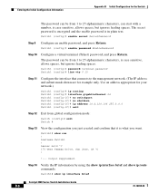
... enable secret password, and press Return. 78-18039-02 Catalyst 4900 Series Switch Installation Guide B-5 Switch# clock set location information in privileged EXEC mode. Appendix B Initial Configuration for the Switch Entering the Initial Configuration Information Performing the Initial Configuration Follow these steps to complete the initial configuration for the switch: Step 1 Step 2 Step 3 Step 4 Step 5 Step 6 At the terminal prompt...
... enable secret password, and press Return. 78-18039-02 Catalyst 4900 Series Switch Installation Guide B-5 Switch# clock set location information in privileged EXEC mode. Appendix B Initial Configuration for the Switch Entering the Initial Configuration Information Performing the Initial Configuration Follow these steps to complete the initial configuration for the switch: Step 1 Step 2 Step 3 Step 4 Step 5 Step 6 At the terminal prompt...
Installation Guide
Page 84
... enable password, and press Return. Switch1 (config)# enable password EnablePassword Step 10 Configure a virtual terminal (Telnet) password, and press Return. Output suppressed. The secret password is encrypted and...configuration mode: Switch (config)# exit Switch # Step 13 View the configuration you want. Entering the Initial Configuration Information Appendix B Initial Configuration for the Switch The password can start with a number, is case sensitive, allows spaces, but ignores leading spaces. Switch1# show ip interface brief Catalyst 4900 Series Switch Installation Guide...
... enable password, and press Return. Switch1 (config)# enable password EnablePassword Step 10 Configure a virtual terminal (Telnet) password, and press Return. Output suppressed. The secret password is encrypted and...configuration mode: Switch (config)# exit Switch # Step 13 View the configuration you want. Entering the Initial Configuration Information Appendix B Initial Configuration for the Switch The password can start with a number, is case sensitive, allows spaces, but ignores leading spaces. Switch1# show ip interface brief Catalyst 4900 Series Switch Installation Guide...
Installation Guide
Page 85
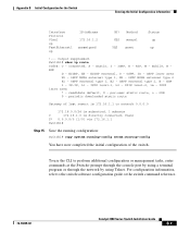
... Interface Protocol Vlan1 up FastEthernet1 up !--- static, I - EIGRP, EX - EGP i - To use the CLI to the switch software configuration guide or the switch command reference. 78-18039-02 Catalyst 4900 Series Switch Installation Guide B-7 IS-IS, L1 - connected, S - periodic downloaded static route Gateway of last resort is 172.16.1.1 to network 0.0.0.0 172.16.0.0/24 is subnetted, 1 subnets...
... Interface Protocol Vlan1 up FastEthernet1 up !--- static, I - EIGRP, EX - EGP i - To use the CLI to the switch software configuration guide or the switch command reference. 78-18039-02 Catalyst 4900 Series Switch Installation Guide B-7 IS-IS, L1 - connected, S - periodic downloaded static route Gateway of last resort is 172.16.1.1 to network 0.0.0.0 172.16.0.0/24 is subnetted, 1 subnets...

Installation Guide
Page 86
Entering the Initial Configuration Information Appendix B Initial Configuration for the Switch Catalyst 4900 Series Switch Installation Guide B-8 78-18039-02
Entering the Initial Configuration Information Appendix B Initial Configuration for the Switch Catalyst 4900 Series Switch Installation Guide B-8 78-18039-02


