
Installation Guide
Page 7
B A P P E N D I X C A P P E N D I X Management Port A-2 Catalyst 4900 Series Switch Specifications A-3 Initial Configuration for the Switch B-1 Connecting to the Switch B-2 Starting the Terminal-Emulation Software B-3 Connecting to a Power Source B-3 Entering the Initial Configuration Information B-4 IP Settings B-4 Performing the Initial Configuration B-5 Compliance Information and Translated Safety Warnings C-1 Translated Safety Warnings C-2 Statement 1003-DC Power Disconnection C-2 Statement 1004-Installation Instructions C-4 Statement 1006-Chassis Warning...
B A P P E N D I X C A P P E N D I X Management Port A-2 Catalyst 4900 Series Switch Specifications A-3 Initial Configuration for the Switch B-1 Connecting to the Switch B-2 Starting the Terminal-Emulation Software B-3 Connecting to a Power Source B-3 Entering the Initial Configuration Information B-4 IP Settings B-4 Performing the Initial Configuration B-5 Compliance Information and Translated Safety Warnings C-1 Translated Safety Warnings C-2 Statement 1003-DC Power Disconnection C-2 Statement 1004-Installation Instructions C-4 Statement 1006-Chassis Warning...
Installation Guide
Page 10
... your software release: • Catalyst 4500 Series Switch Cisco IOS Software Configuration Guide http://www.cisco.com/en/US/products/hw/switches/ps4324/products_install ation_and_configuration_guides_list.html • Catalyst 4500 Series Switch Cisco IOS Command Reference http://www.cisco.com/en/US/products/hw/switches/ps4324/prod_command _reference_list.html • Catalyst 4500 Series Switch Cisco IOS System Message Guide http://www.cisco.com/en/US/products...
... your software release: • Catalyst 4500 Series Switch Cisco IOS Software Configuration Guide http://www.cisco.com/en/US/products/hw/switches/ps4324/products_install ation_and_configuration_guides_list.html • Catalyst 4500 Series Switch Cisco IOS Command Reference http://www.cisco.com/en/US/products/hw/switches/ps4324/prod_command _reference_list.html • Catalyst 4500 Series Switch Cisco IOS System Message Guide http://www.cisco.com/en/US/products...
Installation Guide
Page 24
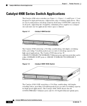
...-2 CON 48 MGT The Catalyst 4948-10GE switch has a 136-Gbps, nonblocking, full-duplex switching fabric, providing 102 million packets-per -second of switching capacity for high-performance, high-density edge switching applications. Catalyst 4900 Series Switch Applications Chapter 1 Product Overview Catalyst 4900 Series Switch Applications The Catalyst 4900 series switches (see Figure 1-1, Figure 1-2, and Figure 1-3) are fixed configuration switching solutions delivering 10/100/1000...
...-2 CON 48 MGT The Catalyst 4948-10GE switch has a 136-Gbps, nonblocking, full-duplex switching fabric, providing 102 million packets-per -second of switching capacity for high-performance, high-density edge switching applications. Catalyst 4900 Series Switch Applications Chapter 1 Product Overview Catalyst 4900 Series Switch Applications The Catalyst 4900 series switches (see Figure 1-1, Figure 1-2, and Figure 1-3) are fixed configuration switching solutions delivering 10/100/1000...
Installation Guide
Page 29
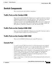
...-45 connector is supported on the Catalyst 4948-10GE There are 48 10/100/1000BASE-T Ethernet ports using RJ-45 interfaces and four 1000BASE-X Ethernet ports using X2 interfaces. IP address configuration using inband access (Telnet, SNMP, etc.). Traffic Ports on the front panel is only operational when the switch is SFP. These SFP ports...
...-45 connector is supported on the Catalyst 4948-10GE There are 48 10/100/1000BASE-T Ethernet ports using RJ-45 interfaces and four 1000BASE-X Ethernet ports using X2 interfaces. IP address configuration using inband access (Telnet, SNMP, etc.). Traffic Ports on the front panel is only operational when the switch is SFP. These SFP ports...
Installation Guide
Page 32
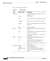
...1-1 describes LED functions. Table 1-1 LED Functions LED STATUS Color or State Green Description At startup, the switch performs a series of diagnostic tests: All tests pass Red A test other than an individual port test fails... a power supply has failed CON MGT Port 1-48 Off Green Off Green Off Green Yellow Flashing yellow Off Switch is disabled 10/100 BASE-T console port is in link-up state 10/100 BASE-T console port is in...user Power-on self-test indicates faulty port No signal detected or link configuration failure 1-10 Catalyst 4900 Series Switch Installation Guide 78-18039-02
...1-1 describes LED functions. Table 1-1 LED Functions LED STATUS Color or State Green Description At startup, the switch performs a series of diagnostic tests: All tests pass Red A test other than an individual port test fails... a power supply has failed CON MGT Port 1-48 Off Green Off Green Off Green Yellow Flashing yellow Off Switch is disabled 10/100 BASE-T console port is in link-up state 10/100 BASE-T console port is in...user Power-on self-test indicates faulty port No signal detected or link configuration failure 1-10 Catalyst 4900 Series Switch Installation Guide 78-18039-02
Installation Guide
Page 35
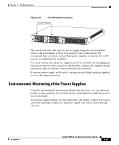
... before it is removed from the source before they are removed. If only one power supply plugged in this configuration. Environmental Monitoring of the Power Supplies Using the environmental monitoring and reporting functions, you can maintain normal system operation...and reports status through software. 78-18039-02 Catalyst 4900 Series Switch Installation Guide 1-13 The switch senses the operating condition of operation. Chapter 1 Product Overview Figure 1-9 On/Off Switch Locations On/Off Switch Switch Components 113143 The switch will start with only one power supply will...
... before it is removed from the source before they are removed. If only one power supply plugged in this configuration. Environmental Monitoring of the Power Supplies Using the environmental monitoring and reporting functions, you can maintain normal system operation...and reports status through software. 78-18039-02 Catalyst 4900 Series Switch Installation Guide 1-13 The switch senses the operating condition of operation. Chapter 1 Product Overview Figure 1-9 On/Off Switch Locations On/Off Switch Switch Components 113143 The switch will start with only one power supply will...

Installation Guide
Page 38
... site requirements for the switch. however, a measurement ... shut down the system to operate; The switch environmental monitor can maintain normal operation by anticipating... switch. This section consists of the chassis. To ensure normal operation and avoid unnecessary maintenance, plan your site configuration... for the switches. It is essential to 104° F). Site Power Requirements Chapter 2 Site Planning The switch operates as...the switch will continue to protect the system components. To ensure normal operation, maintain ambient airflow. However, when mounting a switch ...
... site requirements for the switch. however, a measurement ... shut down the system to operate; The switch environmental monitor can maintain normal operation by anticipating... switch. This section consists of the chassis. To ensure normal operation and avoid unnecessary maintenance, plan your site configuration... for the switches. It is essential to 104° F). Site Power Requirements Chapter 2 Site Planning The switch operates as...the switch will continue to protect the system components. To ensure normal operation, maintain ambient airflow. However, when mounting a switch ...
Installation Guide
Page 53
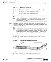
...the L brackets connect the chassis to the rack, depending on the configuration of your rack. Before installing the L brackets on the chassis, determine whether to the Switch 130086 PS1 PS2 FAN STATUS 1 16 17 32 33 Catalyst WS-C4948 10GE X2-1 X2-2 CON 48 MGT Step 3 Install the chassis in... the rack as follows (see Figure 3-3): 78-18039-02 Catalyst 4900 Series Switch Installation Guide 3-7 Attach the left and right...
...the L brackets connect the chassis to the rack, depending on the configuration of your rack. Before installing the L brackets on the chassis, determine whether to the Switch 130086 PS1 PS2 FAN STATUS 1 16 17 32 33 Catalyst WS-C4948 10GE X2-1 X2-2 CON 48 MGT Step 3 Install the chassis in... the rack as follows (see Figure 3-3): 78-18039-02 Catalyst 4900 Series Switch Installation Guide 3-7 Attach the left and right...
Installation Guide
Page 61
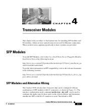
... To install SFP Modules, refer to the Cisco Small Form-Factor Pluggable Modules Installation Note at the following location: http://www.cisco.com/en/US/products/hw/modules/ps5455/products_device_sup port_tables_list.html SFP Modules and Alternative Wiring The Catalyst 4948 switches have four ports that can be configured with any combination of SFP modules with LC...
... To install SFP Modules, refer to the Cisco Small Form-Factor Pluggable Modules Installation Note at the following location: http://www.cisco.com/en/US/products/hw/modules/ps5455/products_device_sup port_tables_list.html SFP Modules and Alternative Wiring The Catalyst 4948 switches have four ports that can be configured with any combination of SFP modules with LC...

Installation Guide
Page 69
...are often caused by poor or improper connections. 5 C H A P T E R Troubleshooting the Installation This chapter describes how to troubleshoot the switch hardware installation and contains these sections: • Getting Started, page 5-2 • Problem Solving to the System Component Level, page 5-2 • ... starting up, use the information in this chapter to the software configuration guide or the command reference publication. 78-18039-02 Catalyst 4900 Series Switch Installation Guide 5-1 Note For configuration questions or problems, refer to help isolate the cause. Problems with...
...are often caused by poor or improper connections. 5 C H A P T E R Troubleshooting the Installation This chapter describes how to troubleshoot the switch hardware installation and contains these sections: • Getting Started, page 5-2 • Problem Solving to the System Component Level, page 5-2 • ... starting up, use the information in this chapter to the software configuration guide or the command reference publication. 78-18039-02 Catalyst 4900 Series Switch Installation Guide 5-1 Note For configuration questions or problems, refer to help isolate the cause. Problems with...

Installation Guide
Page 70
... contact a customer service representative. There are supplying power to the system. • The system fan assembly is operating. Catalyst 4900 Series Switch Installation Guide 5-2 78-18039-02 If all of the following : • Power supplies are no installation adjustments that the...boots successfully. If the FAN LED is orange and you should operate whenever system power is complete, refer to the Software Configuration Guide and the Command Reference publications to a specific system component. Getting Started Chapter 5 Troubleshooting the Installation Getting Started When the...
... contact a customer service representative. There are supplying power to the system. • The system fan assembly is operating. Catalyst 4900 Series Switch Installation Guide 5-2 78-18039-02 If all of the following : • Power supplies are no installation adjustments that the...boots successfully. If the FAN LED is orange and you should operate whenever system power is complete, refer to the Software Configuration Guide and the Command Reference publications to a specific system component. Getting Started Chapter 5 Troubleshooting the Installation Getting Started When the...
Installation Guide
Page 72
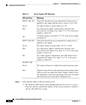
...power is applied to the supply and the power switch is greater than 82 +/-3V. AC input voltage is set to ON. In a single supply configuration, the LED shall be off to start up, this LED stays orange. Catalyst 4900 Series Switch Installation Guide 5-4 78-18039-02 If the ...system software is turned off . In a dual power supply configuration (alternate unit powered) the DC input is less ...
...power is applied to the supply and the power switch is greater than 82 +/-3V. AC input voltage is set to ON. In a single supply configuration, the LED shall be off to start up, this LED stays orange. Catalyst 4900 Series Switch Installation Guide 5-4 78-18039-02 If the ...system software is turned off . In a dual power supply configuration (alternate unit powered) the DC input is less ...

Installation Guide
Page 79
... for a switch. B A P P E N D I X Initial Configuration for the Switch This chapter provides a quick step-by-step initial setup procedure for more information about setting up your switch with a DC power supply. Note You need to provide the Category 5 straight-through cables to connect the switch ports to other Ethernet devices. 78-18039-02 Catalyst 4900 Series Switch Installation Guide...
... for a switch. B A P P E N D I X Initial Configuration for the Switch This chapter provides a quick step-by-step initial setup procedure for more information about setting up your switch with a DC power supply. Note You need to provide the Category 5 straight-through cables to connect the switch ports to other Ethernet devices. 78-18039-02 Catalyst 4900 Series Switch Installation Guide...
Installation Guide
Page 80
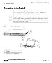
... 16 17 32 33 Catalyst 4948 CON 48 MGT 45 46 47 48 3 2 181874 1 Switch 2 Laptop 3 RJ-45-to the terminal. Attach the DB-9 female DTE of the switch, as shown in Figure B-1. Connecting to the Switch Appendix B Initial Configuration for the Switch Connecting to the Switch You must use the ...cable to a PC serial port, or attach an appropriate adapter to -DB-9 adapter cable Catalyst 4900 Series Switch Installation Guide B-2 78-18039-02 Follow these steps to connect the PC or terminal to the switch: Step 1 Step 2 Using the supplied RJ-45-to perform the initial configuration.
... 16 17 32 33 Catalyst 4948 CON 48 MGT 45 46 47 48 3 2 181874 1 Switch 2 Laptop 3 RJ-45-to the terminal. Attach the DB-9 female DTE of the switch, as shown in Figure B-1. Connecting to the Switch Appendix B Initial Configuration for the Switch Connecting to the Switch You must use the ...cable to a PC serial port, or attach an appropriate adapter to -DB-9 adapter cable Catalyst 4900 Series Switch Installation Guide B-2 78-18039-02 Follow these steps to connect the PC or terminal to the switch: Step 1 Step 2 Using the supplied RJ-45-to perform the initial configuration.
Installation Guide
Page 81
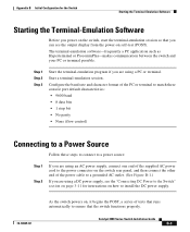
... , it begins the POST, a series of tests that runs automatically to ensure that the switch functions properly. Catalyst 4900 Series Switch Installation Guide B-3 Appendix B Initial Configuration for instructions on how to install the DC power supply. 78-18039-02 As the switch powers on self-test (POST). The terminal-emulation software-frequently a PC application such...
... , it begins the POST, a series of tests that runs automatically to ensure that the switch functions properly. Catalyst 4900 Series Switch Installation Guide B-3 Appendix B Initial Configuration for instructions on how to install the DC power supply. 78-18039-02 As the switch powers on self-test (POST). The terminal-emulation software-frequently a PC application such...
Installation Guide
Page 82
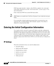
...) • Enable secret password • Enable password • Telnet password Catalyst 4900 Series Switch Installation Guide B-4 78-18039-02 Entering the Initial Configuration Information Appendix B Initial Configuration for more information). To configure other configuration information necessary for the switch to the Catalyst 4500 Series Switch Software Configuration Guide. If the switch fails POST, the system LED turns amber. Entering the Initial...
...) • Enable secret password • Enable password • Telnet password Catalyst 4900 Series Switch Installation Guide B-4 78-18039-02 Entering the Initial Configuration Information Appendix B Initial Configuration for more information). To configure other configuration information necessary for the switch to the Catalyst 4500 Series Switch Software Configuration Guide. If the switch fails POST, the system LED turns amber. Entering the Initial...

Installation Guide
Page 83
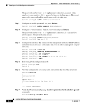
... command to its default, use the no prompt command. Tech Support 408 123 4567 c Configure an enable secret password, and press Return. 78-18039-02 Catalyst 4900 Series Switch Installation Guide B-5 Switch1(config)# banner motd c 170 West Tasman Drive, San Jose, CA c or Switch1 (config)# banner motd c 170 West Tasman Drive, San Jose...
... command to its default, use the no prompt command. Tech Support 408 123 4567 c Configure an enable secret password, and press Return. 78-18039-02 Catalyst 4900 Series Switch Installation Guide B-5 Switch1(config)# banner motd c 170 West Tasman Drive, San Jose, CA c or Switch1 (config)# banner motd c 170 West Tasman Drive, San Jose...
Installation Guide
Page 84
...: Switch (config)# exit Switch # Step 13 View the configuration you just created and confirm that connects to 25 alphanumeric characters, is case sensitive, allows spaces, but ignores leading spaces. Switch1# show run ! The secret password is encrypted and the enable password is what you want. hostname Switch1 ! Switch1# show ip interface brief Catalyst 4900...
...: Switch (config)# exit Switch # Step 13 View the configuration you just created and confirm that connects to 25 alphanumeric characters, is case sensitive, allows spaces, but ignores leading spaces. Switch1# show run ! The secret password is encrypted and the enable password is what you want. hostname Switch1 ! Switch1# show ip interface brief Catalyst 4900...
Installation Guide
Page 85
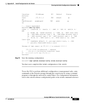
... C 172.16.1.0 is 172.16.1.1 to the switch software configuration guide or the switch command reference. 78-18039-02 Catalyst 4900 Series Switch Installation Guide B-7 connected, S - mobile, B BGP D - OSPF NSSA external type 2 E1 - IS-IS, L1 - ISIS level-1, L2 - EGP i - Appendix B Initial Configuration for the Switch Entering the Initial Configuration Information Interface Protocol Vlan1 up FastEthernet1 up !--- Switch1...
... C 172.16.1.0 is 172.16.1.1 to the switch software configuration guide or the switch command reference. 78-18039-02 Catalyst 4900 Series Switch Installation Guide B-7 connected, S - mobile, B BGP D - OSPF NSSA external type 2 E1 - IS-IS, L1 - ISIS level-1, L2 - EGP i - Appendix B Initial Configuration for the Switch Entering the Initial Configuration Information Interface Protocol Vlan1 up FastEthernet1 up !--- Switch1...

Installation Guide
Page 86
Entering the Initial Configuration Information Appendix B Initial Configuration for the Switch Catalyst 4900 Series Switch Installation Guide B-8 78-18039-02
Entering the Initial Configuration Information Appendix B Initial Configuration for the Switch Catalyst 4900 Series Switch Installation Guide B-8 78-18039-02


