
Installation Guide
Page 8
...) C-2 Attaching the Cisco RPS (model PWR300-AC-RPS-N1) C-4 Service Personnel Warning C-5 Qualified Personnel Warning C-7 Installation Instructions Warning C-9 Jewelry Removal Warning C-10 Stacking the Chassis Warning C-13 Main Disconnecting Device C-15 Overtemperature Warning C-16 TN Power Warning C-19 Ground Connection Warning C-20 Circuit Breaker (15A) Warning C-21 Catalyst 3500 Series XL Hardware Installation...
...) C-2 Attaching the Cisco RPS (model PWR300-AC-RPS-N1) C-4 Service Personnel Warning C-5 Qualified Personnel Warning C-7 Installation Instructions Warning C-9 Jewelry Removal Warning C-10 Stacking the Chassis Warning C-13 Main Disconnecting Device C-15 Overtemperature Warning C-16 TN Power Warning C-19 Ground Connection Warning C-20 Circuit Breaker (15A) Warning C-21 Catalyst 3500 Series XL Hardware Installation...

Installation Guide
Page 12
It also describes how to the switch. Catalyst 3500 Series XL Hardware Installation Guide xii 78-6456-04 Chapter 2, "Installing and Starting Up the Switch," contains the procedures for the switches and the regulatory agency approvals. Examples use these conventions:... brackets (< >). Appendix B, "Connector and Cable Specifications," describes the connectors, cables, and adapters that might arise when you are installing the switch. Appendix A, "Technical Specifications," lists the physical and environmental specifications for installing a switch on a rack, wall, table, or shelf....
It also describes how to the switch. Catalyst 3500 Series XL Hardware Installation Guide xii 78-6456-04 Chapter 2, "Installing and Starting Up the Switch," contains the procedures for the switches and the regulatory agency approvals. Examples use these conventions:... brackets (< >). Appendix B, "Connector and Cable Specifications," describes the connectors, cables, and adapters that might arise when you are installing the switch. Appendix A, "Technical Specifications," lists the physical and environmental specifications for installing a switch on a rack, wall, table, or shelf....

Installation Guide
Page 25
A feature specific to the Catalyst 3524-PWR XL switch is its ability to provide inline power to Cisco IP Phones. (Phone adapters are stackable 10/100 Ethernet switches to the Catalyst 3524-PWR XL 10/100 switch ports.) Figure 1-1 shows the switch models in different network topologies Features The Catalyst 3500 series XL switches-also referred to as Catalyst 3500 XL switches-are not required when connecting to which you can...
A feature specific to the Catalyst 3524-PWR XL switch is its ability to provide inline power to Cisco IP Phones. (Phone adapters are stackable 10/100 Ethernet switches to the Catalyst 3524-PWR XL 10/100 switch ports.) Figure 1-1 shows the switch models in different network topologies Features The Catalyst 3500 series XL switches-also referred to as Catalyst 3500 XL switches-are not required when connecting to which you can...

Installation Guide
Page 32
... and Cable Specifications." Cisco IP Phones-connected to switches or hubs, use Category 3 and 4 cables, but these features. When connecting the switch to the 10/100 ports on a port, the port Catalyst 3500 Series XL Hardware Installation Guide 1-8 78-6456-04 The 10/100 switch ports can be.... Ports operating at 10 Mbps can control whether or not a Catalyst 3524-PWR XL 10/100 port automatically provides power when a Cisco IP Phone is connected On a per -port priority override. The Catalyst 3548 and 3524-PWR XL switches also support per -port basis, you select the Auto setting for...
... and Cable Specifications." Cisco IP Phones-connected to switches or hubs, use Category 3 and 4 cables, but these features. When connecting the switch to the 10/100 ports on a port, the port Catalyst 3500 Series XL Hardware Installation Guide 1-8 78-6456-04 The 10/100 switch ports can be.... Ports operating at 10 Mbps can control whether or not a Catalyst 3524-PWR XL 10/100 port automatically provides power when a Cisco IP Phone is connected On a per -port priority override. The Catalyst 3548 and 3524-PWR XL switches also support per -port basis, you select the Auto setting for...

Installation Guide
Page 47
...-AC-RPS) to the RPS receptacle. Cisco RPS Connector Specific Cisco RPS models support specific Catalyst 3500 XL switches: • Cisco RPS 600 (model PWR600-AC-RPS)-Supports the Catalyst 3512, 3524, 3548, and 3508 XL switches • Cisco RPS 300 (model PWR300-AC-RPS)-Supports the Catalyst 3524-PWR XL switch RPS Connector on the Cisco RPS 600, refer to the Cisco Redundant Power System Hardware Installation Guide. 78...
...-AC-RPS) to the RPS receptacle. Cisco RPS Connector Specific Cisco RPS models support specific Catalyst 3500 XL switches: • Cisco RPS 600 (model PWR600-AC-RPS)-Supports the Catalyst 3512, 3524, 3548, and 3508 XL switches • Cisco RPS 300 (model PWR300-AC-RPS)-Supports the Catalyst 3524-PWR XL switch RPS Connector on the Cisco RPS 600, refer to the Cisco Redundant Power System Hardware Installation Guide. 78...

Installation Guide
Page 48
...help for up of four web-based applications that adapter from Cisco. You use the Visual Switch Manager (VSM) application to a terminal. Management Options Chapter 1 Product Overview RPS Connector on the Catalyst 3524-PWR XL Switch The Cisco RPS 300 (model PWR300-AC-RPS) has two output ...Catalyst 3500 XL switch to create, monitor, and configure a cluster of the console port and the supplied rollover cable and DB-9 adapter. Although it supports up to six switches, it can power only one of 300W. For console port and adapter pinout information, see the "Cable and Adapter Specifications...
...help for up of four web-based applications that adapter from Cisco. You use the Visual Switch Manager (VSM) application to a terminal. Management Options Chapter 1 Product Overview RPS Connector on the Catalyst 3524-PWR XL Switch The Cisco RPS 300 (model PWR300-AC-RPS) has two output ...Catalyst 3500 XL switch to create, monitor, and configure a cluster of the console port and the supplied rollover cable and DB-9 adapter. Although it supports up to six switches, it can power only one of 300W. For console port and adapter pinout information, see the "Cable and Adapter Specifications...

Installation Guide
Page 65
... for Installation Warning This equipment is within the ranges listed in Appendix A, "Technical Specifications." 78-6456-04 Catalyst 3500 Series XL Hardware Installation Guide 2-7 For specific cable lengths, refer to the document that came with your GBICs. • For... the GigaStack GBIC ports, cable lengths from the switch to the connected devices are up to 100 meters. • For 1000BaseX ports, cable lengths from the switch...
... for Installation Warning This equipment is within the ranges listed in Appendix A, "Technical Specifications." 78-6456-04 Catalyst 3500 Series XL Hardware Installation Guide 2-7 For specific cable lengths, refer to the document that came with your GBICs. • For... the GigaStack GBIC ports, cable lengths from the switch to the connected devices are up to 100 meters. • For 1000BaseX ports, cable lengths from the switch...

Installation Guide
Page 81
...application such as Hyperterminal or Procomm Plus-makes communication between the switch and your PC- See the Cisco IOS Desktop Switching Software Configuration Guide for instructions. 78-6456-04 Catalyst 3500 Series XL Hardware Installation Guide 2-23 The PC or terminal must support VT100... Adapter Specifications" section on the GigaStack GBIC connections and configuration scenarios, see the Catalyst GigaStack Gigabit Interface Converter Hardware Installation Guide. or terminal-emulation software is configured to the switch, you have gained access to communicate with the switch via ...
...application such as Hyperterminal or Procomm Plus-makes communication between the switch and your PC- See the Cisco IOS Desktop Switching Software Configuration Guide for instructions. 78-6456-04 Catalyst 3500 Series XL Hardware Installation Guide 2-23 The PC or terminal must support VT100... Adapter Specifications" section on the GigaStack GBIC connections and configuration scenarios, see the Catalyst GigaStack Gigabit Interface Converter Hardware Installation Guide. or terminal-emulation software is configured to the switch, you have gained access to communicate with the switch via ...

Installation Guide
Page 84
...Cisco. For console port and adapter pinout information, see the "Cable and Adapter Specifications" section on page B-4. The data characteristics are 9600 baud, 8 data bits, 1 stop bit, and no ]: y If this procedure to create an initial configuration for the switch, and press Return: 2-26 Catalyst 3500 Series XL... Hardware Installation Guide 78-6456-04 You need to provide a RJ-45-to-DB-25 female DTE adapter if you like to the switch console port. Enter setup, and press Return...
...Cisco. For console port and adapter pinout information, see the "Cable and Adapter Specifications" section on page B-4. The data characteristics are 9600 baud, 8 data bits, 1 stop bit, and no ]: y If this procedure to create an initial configuration for the switch, and press Return: 2-26 Catalyst 3500 Series XL... Hardware Installation Guide 78-6456-04 You need to provide a RJ-45-to-DB-25 female DTE adapter if you like to the switch console port. Enter setup, and press Return...

Installation Guide
Page 97
Table A-1 Technical Specifications for the Catalyst 3500 series XL switches. A A P P E N D I X Technical Specifications 78-6456-04 Table A-1, Table A-2, and Table A-3, list the technical specifications for the Catalyst 3508G XL Switch Environmental Ranges Operating temperature Storage temperature Operating humidity Operating altitude Storage altitude Power Requirements AC input voltage DC ...3A 82.2W 280 Btus per hour 12 lb (5.45 kg) 1.75 x 16 x 17.5 in. (4.45 x 40.46 x 44.45 cm) Catalyst 3500 Series XL Hardware Installation Guide A-1 Table A-4 lists the regulatory agency approvals.
Table A-1 Technical Specifications for the Catalyst 3500 series XL switches. A A P P E N D I X Technical Specifications 78-6456-04 Table A-1, Table A-2, and Table A-3, list the technical specifications for the Catalyst 3508G XL Switch Environmental Ranges Operating temperature Storage temperature Operating humidity Operating altitude Storage altitude Power Requirements AC input voltage DC ...3A 82.2W 280 Btus per hour 12 lb (5.45 kg) 1.75 x 16 x 17.5 in. (4.45 x 40.46 x 44.45 cm) Catalyst 3500 Series XL Hardware Installation Guide A-1 Table A-4 lists the regulatory agency approvals.

Installation Guide
Page 98
Appendix A Technical Specifications Table A-2 Technical Specifications for the Catalyst 3512, 3524, and 3548 XL Switches Catalyst 3512 XL Catalyst 3524 XL Catalyst 3548 XL Environmental Ranges Operating temperature 32 to 113°F (0 to 45°C) 32 to 113°F (0 to 45°C) 32 to 113°F (0 to 45°C) ....82 x 17.5 in. 1.73 x 15.34 x 17.5 in D x W) (4.45 x 30.02 x 44.45 cm) (4.45 x 30.02 x 44.45 cm) (4.39 x 39.0 x 44.45 cm) Catalyst 3500 Series XL Hardware Installation Guide A-2 78-6456-04
Appendix A Technical Specifications Table A-2 Technical Specifications for the Catalyst 3512, 3524, and 3548 XL Switches Catalyst 3512 XL Catalyst 3524 XL Catalyst 3548 XL Environmental Ranges Operating temperature 32 to 113°F (0 to 45°C) 32 to 113°F (0 to 45°C) 32 to 113°F (0 to 45°C) ....82 x 17.5 in. 1.73 x 15.34 x 17.5 in D x W) (4.45 x 30.02 x 44.45 cm) (4.45 x 30.02 x 44.45 cm) (4.39 x 39.0 x 44.45 cm) Catalyst 3500 Series XL Hardware Installation Guide A-2 78-6456-04

Installation Guide
Page 99
Appendix A Technical Specifications Table A-3 Technical Specifications for the Catalyst 3524-PWR XL Switch Environmental Ranges Operating temperature 32 to 113°F (0 to 45°C) Storage temperature -4 to 149°F (-10 to 65°C) Operating humidity 10 to 85% (... the number of IP phones connected. 325W represents 24 IP phones connected. Table A-4 Catalyst 3500 Series XL Agency Approvals Safety EMC UL to UL 1950, Third Edition FCC Part 15 Class A c-UL to CAN/CSA 22.2 No. 950-95, Third Edition EN 55022 Class A (CISPR 22 Class A) TUV/GS to EN 60950 with Amendment...
Appendix A Technical Specifications Table A-3 Technical Specifications for the Catalyst 3524-PWR XL Switch Environmental Ranges Operating temperature 32 to 113°F (0 to 45°C) Storage temperature -4 to 149°F (-10 to 65°C) Operating humidity 10 to 85% (... the number of IP phones connected. 325W represents 24 IP phones connected. Table A-4 Catalyst 3500 Series XL Agency Approvals Safety EMC UL to UL 1950, Third Edition FCC Part 15 Class A c-UL to CAN/CSA 22.2 No. 950-95, Third Edition EN 55022 Class A (CISPR 22 Class A) TUV/GS to EN 60950 with Amendment...

Installation Guide
Page 100
Appendix A Technical Specifications Catalyst 3500 Series XL Hardware Installation Guide A-4 78-6456-04
Appendix A Technical Specifications Catalyst 3500 Series XL Hardware Installation Guide A-4 78-6456-04

Installation Guide
Page 101
...Cisco IP Phones, you use a crossover cable. (Figure B-4 illustrates the crossover cable schematics.) Note Use a straight-through cable and adapter can be attached to the port. Figure B-1 shows the pinout. APPENDIX B Connector and Cable Specifications This appendix describes the Catalyst 3500 XL switch ...ports and the cables and adapters that you use to connect the switch to other switches or repeaters, ensure that a straight-through cable to connect ...
...Cisco IP Phones, you use a crossover cable. (Figure B-4 illustrates the crossover cable schematics.) Note Use a straight-through cable and adapter can be attached to the port. Figure B-1 shows the pinout. APPENDIX B Connector and Cable Specifications This appendix describes the Catalyst 3500 XL switch ...ports and the cables and adapters that you use to connect the switch to other switches or repeaters, ensure that a straight-through cable to connect ...

Installation Guide
Page 102
Figure B-2 1000BaseX SC Connector H8707 Tx Rx Catalyst 3500 Series XL Hardware Installation Guide B-2 78-6456-04 Connector Specifications Appendix B Connector and Cable Specifications Figure B-1 10/100 Port Pinouts Pin Label 1 RD+ 2 RD- 3 TD+ 4 NC 5 NC 6 TD- 7 NC 8 NC 12345678 H5318 1000BaseX Ports 1000BaseX ports use duplex SC connectors, as shown in Figure B-2.
Figure B-2 1000BaseX SC Connector H8707 Tx Rx Catalyst 3500 Series XL Hardware Installation Guide B-2 78-6456-04 Connector Specifications Appendix B Connector and Cable Specifications Figure B-1 10/100 Port Pinouts Pin Label 1 RD+ 2 RD- 3 TD+ 4 NC 5 NC 6 TD- 7 NC 8 NC 12345678 H5318 1000BaseX Ports 1000BaseX ports use duplex SC connectors, as shown in Figure B-2.

Installation Guide
Page 103
...6456-04 Catalyst 3500 Series XL Hardware Installation Guide B-3 Figure B-3 GigaStack Connector 22084 The GigaStack GBIC cables are used to connect the console port of the switch to a terminal. Appendix B Connector and Cable Specifications Connector Specifications Gigastack Port... The GigaStack Gigabit Interface Converter (GBIC) uses proprietary connectors, as shown in Table B-1 and Table B-2. You can order a kit (part number ACS-DSBUASYN=) containing that adapter from Cisco...
...6456-04 Catalyst 3500 Series XL Hardware Installation Guide B-3 Figure B-3 GigaStack Connector 22084 The GigaStack GBIC cables are used to connect the console port of the switch to a terminal. Appendix B Connector and Cable Specifications Connector Specifications Gigastack Port... The GigaStack Gigabit Interface Converter (GBIC) uses proprietary connectors, as shown in Table B-1 and Table B-2. You can order a kit (part number ACS-DSBUASYN=) containing that adapter from Cisco...

Installation Guide
Page 104
Switch 3 TD+ 6 TD- 1 RD+ 2 RD- 1 RD+ 2 RD- H5579 Figure B-5 Straight-Through Cable Schematic Switch 3 TD+ 6 TD- H5578 Catalyst 3500 Series XL Hardware Installation Guide B-4 78-6456-04 Switch 3 RD+ 6 RD- 1 RD+ 2 RD- 1 TD+ 2 TD- Figure B-4 Crossover Cable Schematic Switch 3 TD+ 6 TD- Cable and Adapter Specifications Appendix B Connector and Cable Specifications Cable and Adapter Specifications Crossover and Straight-Through Cable Pinouts The schematics of crossover and straight-through cables are shown in Figure B-4 and Figure B-5.
Switch 3 TD+ 6 TD- 1 RD+ 2 RD- 1 RD+ 2 RD- H5579 Figure B-5 Straight-Through Cable Schematic Switch 3 TD+ 6 TD- H5578 Catalyst 3500 Series XL Hardware Installation Guide B-4 78-6456-04 Switch 3 RD+ 6 RD- 1 RD+ 2 RD- 1 TD+ 2 TD- Figure B-4 Crossover Cable Schematic Switch 3 TD+ 6 TD- Cable and Adapter Specifications Appendix B Connector and Cable Specifications Cable and Adapter Specifications Crossover and Straight-Through Cable Pinouts The schematics of crossover and straight-through cables are shown in Figure B-4 and Figure B-5.

Installation Guide
Page 105
... Cable Pin 1 Pin 1 on one connector and pin 8 on the outside of the cable. Pin 8 H10632 78-6456-04 Catalyst 3500 Series XL Hardware Installation Guide B-5 Appendix B Connector and Cable Specifications Cable and Adapter Specifications Rollover Cable and Adapter Pinouts Identifying a Rollover Cable To identify a rollover cable, compare the two modular ends of the...
... Cable Pin 1 Pin 1 on one connector and pin 8 on the outside of the cable. Pin 8 H10632 78-6456-04 Catalyst 3500 Series XL Hardware Installation Guide B-5 Appendix B Connector and Cable Specifications Cable and Adapter Specifications Rollover Cable and Adapter Pinouts Identifying a Rollover Cable To identify a rollover cable, compare the two modular ends of the...

Installation Guide
Page 106
... shows how to connect the console port to -DB-9 female DTE adapter. Figure B-7 Connecting the Console Port to a PC PC Catalyst 3500 series XL switch 22003 RJ-45-to-RJ-45 rollover cable RJ-45-to-DB-9 adapter (labeled TERMINAL) Table B-1 Console Port Signaling and Cabling ...3 6 GND 4 5 GND 5 4 RxD 6 3 Not connected 7 2 CTS 8 1 RJ-45-to a PC running terminal-emulation software. Cable and Adapter Specifications Appendix B Connector and Cable Specifications Connecting to a PC Use the supplied thin, flat, RJ-45-to-RJ-45 rollover cable and RJ-45-to-DB-9 female DTE adapter...
... shows how to connect the console port to -DB-9 female DTE adapter. Figure B-7 Connecting the Console Port to a PC PC Catalyst 3500 series XL switch 22003 RJ-45-to-RJ-45 rollover cable RJ-45-to-DB-9 adapter (labeled TERMINAL) Table B-1 Console Port Signaling and Cabling ...3 6 GND 4 5 GND 5 4 RxD 6 3 Not connected 7 2 CTS 8 1 RJ-45-to a PC running terminal-emulation software. Cable and Adapter Specifications Appendix B Connector and Cable Specifications Connecting to a PC Use the supplied thin, flat, RJ-45-to-RJ-45 rollover cable and RJ-45-to-DB-9 female DTE adapter...
Installation Guide
Page 107
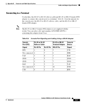
You can order a kit (part number ACS-DSBUASYN=) containing this adapter from Cisco. Table B-2 Console Port Signaling and Cabling Using a DB-25 Adapter Console Port (DTE) RJ-45-to-RJ-45 Rollover Cable Signal RJ-45 Pin RJ-... adapter is not supplied with the switch. Note The RJ-45-to -DB-25 Terminal Adapter DB-25 Pin 5 6 3 7 7 2 20 4 Console Device Signal CTS DSR RxD GND GND TxD DTR RTS 78-6456-04 Catalyst 3500 Series XL Hardware Installation Guide B-7 Appendix B Connector and Cable Specifications Cable and Adapter Specifications Connecting to a Terminal Use the...
You can order a kit (part number ACS-DSBUASYN=) containing this adapter from Cisco. Table B-2 Console Port Signaling and Cabling Using a DB-25 Adapter Console Port (DTE) RJ-45-to-RJ-45 Rollover Cable Signal RJ-45 Pin RJ-... adapter is not supplied with the switch. Note The RJ-45-to -DB-25 Terminal Adapter DB-25 Pin 5 6 3 7 7 2 20 4 Console Device Signal CTS DSR RxD GND GND TxD DTR RTS 78-6456-04 Catalyst 3500 Series XL Hardware Installation Guide B-7 Appendix B Connector and Cable Specifications Cable and Adapter Specifications Connecting to a Terminal Use the...

