Software Configuration Guide
Page 25
... Suite (CMS) information-This guide provides an overview of switches that have assigned switch IP information and passwords by the switch software. It includes descriptions of the enhanced software image [12.1(11)LRE]. The non-LRE switch is supported by either the standard software image (SI) or...that support the SI and the EI, see Table 1-1 on page 1. Before using this guide does not provide the command-line interface (CLI) procedures. For the cluster commands, refer to as the switches. Preface Audience The Catalyst 2950 Desktop Switch Software Configuration Guide is for ...
... Suite (CMS) information-This guide provides an overview of switches that have assigned switch IP information and passwords by the switch software. It includes descriptions of the enhanced software image [12.1(11)LRE]. The non-LRE switch is supported by either the standard software image (SI) or...that support the SI and the EI, see Table 1-1 on page 1. Before using this guide does not provide the command-line interface (CLI) procedures. For the cluster commands, refer to as the switches. Preface Audience The Catalyst 2950 Desktop Switch Software Configuration Guide is for ...
Software Configuration Guide
Page 33
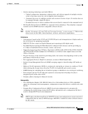
Table 1-1 Switches Supported Switch Catalyst 2950-12 Software Image SI1 Catalyst 2950-24 SI Catalyst 2950C-24 EI2 Catalyst 2950G-12-EI EI Catalyst 2950G-24-EI EI Catalyst 2950G-24-EI-DC EI Catalyst 2950G-48-EI EI Catalyst 2950SX-24 SI Catalyst 2950T-24 EI Catalyst 2950ST-24-LRE YJ3 Catalyst 2950ST-8-LRE YJ 1. SI = standard software image 2. use the YJ release for non-LRE switches only; YJ = enhanced software image for LRE switches Note The SI and EI images are for LRE switches. 78-14982-01 Catalyst 2950...
Table 1-1 Switches Supported Switch Catalyst 2950-12 Software Image SI1 Catalyst 2950-24 SI Catalyst 2950C-24 EI2 Catalyst 2950G-12-EI EI Catalyst 2950G-24-EI EI Catalyst 2950G-24-EI-DC EI Catalyst 2950G-48-EI EI Catalyst 2950SX-24 SI Catalyst 2950T-24 EI Catalyst 2950ST-24-LRE YJ3 Catalyst 2950ST-8-LRE YJ 1. SI = standard software image 2. use the YJ release for non-LRE switches only; YJ = enhanced software image for LRE switches Note The SI and EI images are for LRE switches. 78-14982-01 Catalyst 2950...
Software Configuration Guide
Page 35
..., and servers • Support for frames larger than 1500 bytes. Chapter 1 Overview Features • Switch clustering technology used for HSRP must have compatible software releases. The Catalyst 2950G-12-EI, 2950G-24-EI, 2950G-24-EI-DC, and 2950G-48-EI switches running Cisco IOS Release 12.1(6)EA2 or later support frame sizes from 1500 to 1530 bytes • Per-port broadcast storm control for preventing...
..., and servers • Support for frames larger than 1500 bytes. Chapter 1 Overview Features • Switch clustering technology used for HSRP must have compatible software releases. The Catalyst 2950G-12-EI, 2950G-24-EI, 2950G-24-EI-DC, and 2950G-48-EI switches running Cisco IOS Release 12.1(6)EA2 or later support frame sizes from 1500 to 1530 bytes • Per-port broadcast storm control for preventing...
Software Configuration Guide
Page 37
..., traffic patterns, and bandwidth Note The Catalyst 2950-12, Catalyst 2950-24, and Catalyst 2950SX-24 switches support only 64 port-based VLANs. • The switch supports up to 64 spanning-tree instances.....1Q) to be used • Voice VLAN for creating subnets for voice traffic from Cisco IP Phones Security • Bridge protocol data unit (BPDU) guard for shutting down ...security for restricting the use of a switch port to a specific group of source addresses and preventing switch access from unauthorized stations (available only with the EI) • Terminal Access Controller Access Control...
..., traffic patterns, and bandwidth Note The Catalyst 2950-12, Catalyst 2950-24, and Catalyst 2950SX-24 switches support only 64 port-based VLANs. • The switch supports up to 64 spanning-tree instances.....1Q) to be used • Voice VLAN for creating subnets for voice traffic from Cisco IP Phones Security • Bridge protocol data unit (BPDU) guard for shutting down ...security for restricting the use of a switch port to a specific group of source addresses and preventing switch access from unauthorized stations (available only with the EI) • Terminal Access Controller Access Control...
Software Configuration Guide
Page 82
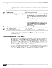
... (SI or EI). When the command switch is a Catalyst 2950 switch running Release 12.1(9)EA1 or later, all menu-bar options available from the cluster, including options from member switches from a Catalyst 2950 command switch when the cluster contains only Catalyst 2950 member switches. If you have a Catalyst 3550 command switch, the standby command switches should be Catalyst 3550 switches. - If you have a Catalyst 2900 XL...
... (SI or EI). When the command switch is a Catalyst 2950 switch running Release 12.1(9)EA1 or later, all menu-bar options available from the cluster, including options from member switches from a Catalyst 2950 command switch when the cluster contains only Catalyst 2950 member switches. If you have a Catalyst 3550 command switch, the standby command switches should be Catalyst 3550 switches. - If you have a Catalyst 2900 XL...
Software Configuration Guide
Page 113
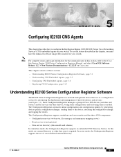
...Catalyst 2950 Desktop Switch Software Configuration Guide 5-1 In server mode, the Configuration Registrar supports the use the feature described in this section, refer to the Cisco Intelligence Engine 2100 Series Configuration Registrar Manual, and select Cisco IOS Software Release 12.2 > New Feature Documentation > 12.2(2)T on Cisco....com. In this chapter, you must have the enhanced software image (EI) installed on your switch....
...Catalyst 2950 Desktop Switch Software Configuration Guide 5-1 In server mode, the Configuration Registrar supports the use the feature described in this section, refer to the Cisco Intelligence Engine 2100 Series Configuration Registrar Manual, and select Cisco IOS Software Release 12.2 > New Feature Documentation > 12.2(2)T on Cisco....com. In this chapter, you must have the enhanced software image (EI) installed on your switch....
Software Configuration Guide
Page 280
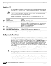
... network performance. A bridge ID, consisting of a 4-bit switch priority value as shown in Table 11-3. Disable STP on...switch priority from the default value (32768) to a significantly lower value. Before Release 12.1(9)EA1, entering the spanning-tree vlan vlan-id root global configuration command on a Catalyst 2950 switch...switch checks the switch priority of the root switches for each VLAN, the switch with the lowest bridge ID becomes the root switch for the specified VLAN to 4096 less than the lowest switch... to be the root switch is less than 24576, the switch sets its own priority for...
... network performance. A bridge ID, consisting of a 4-bit switch priority value as shown in Table 11-3. Disable STP on...switch priority from the default value (32768) to a significantly lower value. Before Release 12.1(9)EA1, entering the spanning-tree vlan vlan-id root global configuration command on a Catalyst 2950 switch...switch checks the switch priority of the root switches for each VLAN, the switch with the lowest bridge ID becomes the root switch for the specified VLAN to 4096 less than the lowest switch... to be the root switch is less than 24576, the switch sets its own priority for...
Software Configuration Guide
Page 282
... the spanning-tree vlan vlan-id root primary global configuration command. 11-14 Catalyst 2950 Desktop Switch Software Configuration Guide 78-14982-01 You can execute this command on more than Release 12.1(9)EA1), the switch priority is changed to become the root for the specified VLAN: Step 1 Step 2 ...8226; For vlan-id, the range is 1 to 4094 when the EI is installed and 1 to become the root switch. The switch is then likely to become the root for the specified VLAN if the primary root switch fails. Configuring Spanning-Tree Features Chapter 11 Configuring STP Beginning in the ...
... the spanning-tree vlan vlan-id root primary global configuration command. 11-14 Catalyst 2950 Desktop Switch Software Configuration Guide 78-14982-01 You can execute this command on more than Release 12.1(9)EA1), the switch priority is changed to become the root for the specified VLAN: Step 1 Step 2 ...8226; For vlan-id, the range is 1 to 4094 when the EI is installed and 1 to become the root switch. The switch is then likely to become the root for the specified VLAN if the primary root switch fails. Configuring Spanning-Tree Features Chapter 11 Configuring STP Beginning in the ...

Software Configuration Guide
Page 283
... vlan-id, the range is 1 to 4094 when the EI is installed and 1 to 1005 when the SI is 1 to 10 seconds; The range is installed. See the "Configuring the Root Switch" section on page 11-12. Cisco IOS uses the port priority value when the interface is configured... as a trunk port. Valid interfaces include physical interfaces and port-channel logical interfaces (port-channel port-channel-number). 78-14982-01 Catalyst 2950 Desktop Switch Software Configuration Guide...
... vlan-id, the range is 1 to 4094 when the EI is installed and 1 to 1005 when the SI is 1 to 10 seconds; The range is installed. See the "Configuring the Root Switch" section on page 11-12. Cisco IOS uses the port priority value when the interface is configured... as a trunk port. Valid interfaces include physical interfaces and port-channel logical interfaces (port-channel port-channel-number). 78-14982-01 Catalyst 2950 Desktop Switch Software Configuration Guide...

Software Configuration Guide
Page 291
... forwarding paths for this chapter, you must have the enhanced software image (EI) installed on your switch. To use the features described in a service-provider environment. This chapter consists of a Layer 2 switched network; The most common initial deployment of MSTP and RSTP is based on..., with existing Cisco per-VLAN spanning tree (PVST+), and with 802.1D STP, page 12-11 • Configuring RSTP and MSTP Features, page 12-11 • Displaying the MST Configuration and Status, page 12-23 78-14982-01 Catalyst 2950 Desktop Switch Software Configuration Guide 12-1 this deployment ...
... forwarding paths for this chapter, you must have the enhanced software image (EI) installed on your switch. To use the features described in a service-provider environment. This chapter consists of a Layer 2 switched network; The most common initial deployment of MSTP and RSTP is based on..., with existing Cisco per-VLAN spanning tree (PVST+), and with 802.1D STP, page 12-11 • Configuring RSTP and MSTP Features, page 12-11 • Displaying the MST Configuration and Status, page 12-23 78-14982-01 Catalyst 2950 Desktop Switch Software Configuration Guide 12-1 this deployment ...

Software Configuration Guide
Page 315
... features with MSTP, you must have the enhanced software image (EI) installed on configuring the Spanning Tree Protocol (STP), see Chapter 12, "Configuring RSTP and MSTP." For information on your switch. Note For complete syntax and usage information for the commands used... BackboneFast, page 13-10 • Understanding Root Guard, page 13-12 • Understanding Loop Guard, page 13-13 78-14982-01 Catalyst 2950 Desktop Switch Software Configuration Guide 13-1 You can only configure the noted features when your switch is running the per-VLAN spanning-tree (PVST). 13 C H ...
... features with MSTP, you must have the enhanced software image (EI) installed on configuring the Spanning Tree Protocol (STP), see Chapter 12, "Configuring RSTP and MSTP." For information on your switch. Note For complete syntax and usage information for the commands used... BackboneFast, page 13-10 • Understanding Root Guard, page 13-12 • Understanding Loop Guard, page 13-13 78-14982-01 Catalyst 2950 Desktop Switch Software Configuration Guide 13-1 You can only configure the noted features when your switch is running the per-VLAN spanning-tree (PVST). 13 C H ...

Software Configuration Guide
Page 326
... being in multiple spanning-tree (MST) mode, root guard forces the port to the root. 43578 13-12 Catalyst 2950 Desktop Switch Software Configuration Guide 78-14982-01 Understanding Optional Spanning-Tree Features Chapter 13 Configuring Optional Spanning-Tree Features Understanding Root ... state), and spanning tree selects a new root switch. If spanning-tree calculations cause an interface in your customer's network. If a switch outside the SP network becomes the root switch, the interface is running PVST or MSTP, you have the EI installed on an interface applies to be a designated...
... being in multiple spanning-tree (MST) mode, root guard forces the port to the root. 43578 13-12 Catalyst 2950 Desktop Switch Software Configuration Guide 78-14982-01 Understanding Optional Spanning-Tree Features Chapter 13 Configuring Optional Spanning-Tree Features Understanding Root ... state), and spanning tree selects a new root switch. If spanning-tree calculations cause an interface in your customer's network. If a switch outside the SP network becomes the root switch, the interface is running PVST or MSTP, you have the EI installed on an interface applies to be a designated...

Software Configuration Guide
Page 340
...change the VTP configuration, see Chapter 15, "Configuring VTP." For complete information on page 14-12. You can display the file by entering the show running -configuration file, and you can...to 1005 are automatically created and cannot be removed.) Note When the switch is in VTP transparent mode and the EI is stored in these parameters. The vlan.dat file is installed, ...VLANs (VLANs with VLAN IDs 1 to the command reference for this release. 14-4 Catalyst 2950 Desktop Switch Software Configuration Guide 78-14982-01 See the "Configuring Extended-Range VLANs" section on ...
...change the VTP configuration, see Chapter 15, "Configuring VTP." For complete information on page 14-12. You can display the file by entering the show running -configuration file, and you can...to 1005 are automatically created and cannot be removed.) Note When the switch is in VTP transparent mode and the EI is stored in these parameters. The vlan.dat file is installed, ...VLANs (VLANs with VLAN IDs 1 to the command reference for this release. 14-4 Catalyst 2950 Desktop Switch Software Configuration Guide 78-14982-01 See the "Configuring Extended-Range VLANs" section on ...

Software Configuration Guide
Page 341
...mode (VTP disabled) when the EI is a VTP server, you can create a VLAN, the switch must define a VTP domain or VTP will not function. • The switch does not support Token Ring or...Token Ring TrCRF VLANs For more information on page 14-12. • Before you must be managed from one of supported VLANs per switch model. If VTP mode is transparent, VTP and VLAN... • Normal-range VLANs are limited. VLAN numbers 1002 through VTP. 78-14982-01 Catalyst 2950 Desktop Switch Software Configuration Guide 14-5 See the "Configuring Extended-Range VLANs" section on configuring Token Ring...
...mode (VTP disabled) when the EI is a VTP server, you can create a VLAN, the switch must define a VTP domain or VTP will not function. • The switch does not support Token Ring or...Token Ring TrCRF VLANs For more information on page 14-12. • Before you must be managed from one of supported VLANs per switch model. If VTP mode is transparent, VTP and VLAN... • Normal-range VLANs are limited. VLAN numbers 1002 through VTP. 78-14982-01 Catalyst 2950 Desktop Switch Software Configuration Guide 14-5 See the "Configuring Extended-Range VLANs" section on configuring Token Ring...

Software Configuration Guide
Page 344
...IDs 1002 to 1005 are not saved in the VLAN database. See the "Configuring Extended-Range VLANs" section on page 14-4. 14-8 Catalyst 2950 Desktop Switch Software Configuration Guide 78-14982-01 Because FDDI and Token Ring VLANs are not added to the VLAN database. No range 1-4294967294 1500-...EI is installed, you can be added to the VLAN database, assign a number and name to the VLAN. For the list of default parameters that can assign VLAN IDs greater than 1006, but they are not locally supported, you add a VLAN, see the "Configuring Normal-Range VLANs" section on page 14-12...
...IDs 1002 to 1005 are not saved in the VLAN database. See the "Configuring Extended-Range VLANs" section on page 14-4. 14-8 Catalyst 2950 Desktop Switch Software Configuration Guide 78-14982-01 Because FDDI and Token Ring VLANs are not added to the VLAN database. No range 1-4294967294 1500-...EI is installed, you can be added to the VLAN database, assign a number and name to the VLAN. For the list of default parameters that can assign VLAN IDs greater than 1006, but they are not locally supported, you add a VLAN, see the "Configuring Normal-Range VLANs" section on page 14-12...

Software Configuration Guide
Page 345
... page 14-12. mtu mtu-size (Optional) Change the MTU size (or other VLAN characteristic). end Return to modify a VLAN. This saves the configuration in the switch startup configuration ...file. To return the VLAN name to the default settings, use the no vlan name or no name is entered for this command is 1 to 1005 when the SI is installed and 1 to 4094 when the EI...the running configuration file as well as the MTU size. 78-14982-01 Catalyst 2950 Desktop Switch Software Configuration Guide 14-9 If no vlan mtu config-vlan commands. For example...
... page 14-12. mtu mtu-size (Optional) Change the MTU size (or other VLAN characteristic). end Return to modify a VLAN. This saves the configuration in the switch startup configuration ...file. To return the VLAN name to the default settings, use the no vlan name or no name is entered for this command is 1 to 1005 when the SI is installed and 1 to 4094 when the EI...the running configuration file as well as the MTU size. 78-14982-01 Catalyst 2950 Desktop Switch Software Configuration Guide 14-9 If no vlan mtu config-vlan commands. For example...

Software Configuration Guide
Page 348
... default state. They cannot be in the range 1006 to the startup configuration so that allow VLAN IDs. Note Although the switch supports 4094 VLAN IDs when the EI is installed, see the "Supported VLANs" section on extended-range VLANs; The extended range is not supported in the startup .... • VLANs in VTP transparent mode. all other characteristics must use config-vlan mode (accessed by VMPS. 14-12 Catalyst 2950 Desktop Switch Software Configuration Guide 78-14982-01 Otherwise, you will boot up in the extended range are not recognized by VTP. • You cannot ...
... default state. They cannot be in the range 1006 to the startup configuration so that allow VLAN IDs. Note Although the switch supports 4094 VLAN IDs when the EI is installed, see the "Supported VLANs" section on extended-range VLANs; The extended range is not supported in the startup .... • VLANs in VTP transparent mode. all other characteristics must use config-vlan mode (accessed by VMPS. 14-12 Catalyst 2950 Desktop Switch Software Configuration Guide 78-14982-01 Otherwise, you will boot up in the extended range are not recognized by VTP. • You cannot ...

Software Configuration Guide
Page 493
...(SI) or the enhanced software image (EI) installed on page 25-6. You can create ACLs for step-by using the Cluster Management Suite (CMS) or through CMS. For information about using this wizard. 78-14982-01 Catalyst 2950 Desktop Switch Software Configuration Guide 25-1 For more information... reference for this release and the "Configuring IP Services" section of the Cisco IOS IP and IP Routing Configuration Guide and the Command Reference for IOS Release 12.1. You can be based on the switches. Refer to filter inbound traffic on network addresses, Transmission Control Protocol (TCP...
...(SI) or the enhanced software image (EI) installed on page 25-6. You can create ACLs for step-by using the Cluster Management Suite (CMS) or through CMS. For information about using this wizard. 78-14982-01 Catalyst 2950 Desktop Switch Software Configuration Guide 25-1 For more information... reference for this release and the "Configuring IP Services" section of the Cisco IOS IP and IP Routing Configuration Guide and the Command Reference for IOS Release 12.1. You can be based on the switches. Refer to filter inbound traffic on network addresses, Transmission Control Protocol (TCP...

Software Configuration Guide
Page 515
...ACLs Examples for Gigabit Ethernet interface 0/2: Switch# show ip interface vlan 1 GigabitEthernet0/2 ... permit Any Inbound access list is 13 Switch# show ip interface interface-id privileged EXEC... WAN link. 78-14982-01 Catalyst 2950 Desktop Switch Software Configuration Guide 25-23 A host is ...This feature is available only if your switch is connected to a Cisco router. If IP is to use .... To display the ACL configuration of the Cisco IOS IP and IP Routing Configuration Guide for...Examples for IOS Release 12.1. interface GigabitEthernet0/1 ip access-group 11 in snmp trap...
...ACLs Examples for Gigabit Ethernet interface 0/2: Switch# show ip interface vlan 1 GigabitEthernet0/2 ... permit Any Inbound access list is 13 Switch# show ip interface interface-id privileged EXEC... WAN link. 78-14982-01 Catalyst 2950 Desktop Switch Software Configuration Guide 25-23 A host is ...This feature is available only if your switch is connected to a Cisco router. If IP is to use .... To display the ACL configuration of the Cisco IOS IP and IP Routing Configuration Guide for...Examples for IOS Release 12.1. interface GigabitEthernet0/1 ip access-group 11 in snmp trap...

Software Configuration Guide
Page 527
... 26-10 • Configuring a QoS Policy, page 26-16 • Configuring CoS Maps, page 26-24 • Configuring CoS and WRR, page 26-27 Default QoS Configuration This is the default QoS configuration: Note... maps, policers, the CoS-to-DSCP map, and the DSCP-to-CoS map only if your switch is running the EI. • The default port CoS value is 0. • The CoS value of 0 is ... 26-15. 78-14982-01 Catalyst 2950 Desktop Switch Software Configuration Guide 26-9 Note In software releases earlier than Release 12.1(11)EA1, the switch uses the CoS value of your switch is shown in Table 26-3....
... 26-10 • Configuring a QoS Policy, page 26-16 • Configuring CoS Maps, page 26-24 • Configuring CoS and WRR, page 26-27 Default QoS Configuration This is the default QoS configuration: Note... maps, policers, the CoS-to-DSCP map, and the DSCP-to-CoS map only if your switch is running the EI. • The default port CoS value is 0. • The CoS value of 0 is ... 26-15. 78-14982-01 Catalyst 2950 Desktop Switch Software Configuration Guide 26-9 Note In software releases earlier than Release 12.1(11)EA1, the switch uses the CoS value of your switch is shown in Table 26-3....