
iP4200 Quick Start Guide
Page 97
...THE PRODUCT CAUSING THE ALLEGED DAMAGE. Appendix CANON U.S.A., INC. LIMITED WARRANTY --- (USA Only) The limited warranty set forth in , Canon USA's user's manual or other documentation, or services performed by someone other than a Canon USA repair facility or ASF. The Product is ...required at the time of the Product. Defective parts or a defective Product returned to a Canon USA repair facility or a Canon USA Authorized Service Facility ("ASF"), and proven to follow operating or maintenance instructions in, or environmental conditions prescribed in the user...
...THE PRODUCT CAUSING THE ALLEGED DAMAGE. Appendix CANON U.S.A., INC. LIMITED WARRANTY --- (USA Only) The limited warranty set forth in , Canon USA's user's manual or other documentation, or services performed by someone other than a Canon USA repair facility or ASF. The Product is ...required at the time of the Product. Defective parts or a defective Product returned to a Canon USA repair facility or a Canon USA Authorized Service Facility ("ASF"), and proven to follow operating or maintenance instructions in, or environmental conditions prescribed in the user...
iP4200 Quick Start Guide
Page 98
... continental United States, Alaska and Hawaii during the limited warranty period, Canon USA offers two hardware support options: Authorized Service Facility Carry-In / Mail-In Service Canon USA's Carry-In/Mail-In Service provides repair or exchange, at : www.canonhelp.com or by Canon USA. CANON USA WILL RETAIN THE DEFECTIVE PRODUCT THAT YOU ORIGINALLY PURCHASED, WHICH SHALL...
... continental United States, Alaska and Hawaii during the limited warranty period, Canon USA offers two hardware support options: Authorized Service Facility Carry-In / Mail-In Service Canon USA's Carry-In/Mail-In Service provides repair or exchange, at : www.canonhelp.com or by Canon USA. CANON USA WILL RETAIN THE DEFECTIVE PRODUCT THAT YOU ORIGINALLY PURCHASED, WHICH SHALL...
Service Manual
Page 1
Revision CANON PIXMA iP4200 072005 XX 0.00-0 Scope This manual has been issued by Canon Inc., to provide the service technicians of products. For this product with the information necessary for qualified persons to your region. PIXMA iP4200 SERVICE MANUAL Revision 0 QY8-13A9-000 COPYRIGHT©2005 CANON INC. The manual covers information applicable in all regions where the product is not applicable to learn technical theory, installation, maintenance, and repair of this reason, it may contain information that is sold.
Revision CANON PIXMA iP4200 072005 XX 0.00-0 Scope This manual has been issued by Canon Inc., to provide the service technicians of products. For this product with the information necessary for qualified persons to your region. PIXMA iP4200 SERVICE MANUAL Revision 0 QY8-13A9-000 COPYRIGHT©2005 CANON INC. The manual covers information applicable in all regions where the product is not applicable to learn technical theory, installation, maintenance, and repair of this reason, it may contain information that is sold.
Service Manual
Page 4
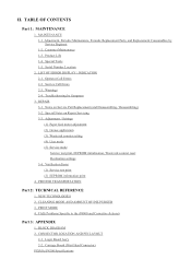
... LOCATION AND PIN LAYOUT 2-1. Carriage Board (Print Head Connector) PIXMA iP4200 Specifications Adjustment, Periodic Maintenance, Periodic Replacement Parts, and Replacement Consumables by Symptom 3. Product Life 1-4. FAQ (Problems Specific to the iP4000 and Corrective Actions) Part 3: APPENDIX 1. Special Tools 1-5. Service Call Errors 2-3. Notes on Repair Servicing 3-3. Verification Items (1) Service test print (2) EEPROM information print 4. LIST OF ERROR...
... LOCATION AND PIN LAYOUT 2-1. Carriage Board (Print Head Connector) PIXMA iP4200 Specifications Adjustment, Periodic Maintenance, Periodic Replacement Parts, and Replacement Consumables by Symptom 3. Product Life 1-4. FAQ (Problems Specific to the iP4000 and Corrective Actions) Part 3: APPENDIX 1. Special Tools 1-5. Service Call Errors 2-3. Notes on Repair Servicing 3-3. Verification Items (1) Service test print (2) EEPROM information print 4. LIST OF ERROR...
Service Manual
Page 17
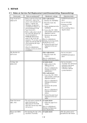
...information print At replacement: 1. Adjustment / Settings, (5) Service mode.] - By attaching the tape at the At replacement: specified 2 locations, After the printer unit is 7% or more, also Settings, (5) Service mode, replace the ink absorber kit for details of ...adjustment.] - Check the ink system EEPROM information function. Settings, (5) Service mode, for discharge of 1 to the 1. 3. Correct the CD / DVD - Adjustment / Settings, (2) Grease application.] After replacement: 1. REPAIR 3-1. Before removal of the logic After replacement: board ass'y, remove ...
...information print At replacement: 1. Adjustment / Settings, (5) Service mode.] - By attaching the tape at the At replacement: specified 2 locations, After the printer unit is 7% or more, also Settings, (5) Service mode, replace the ink absorber kit for details of ...adjustment.] - Check the ink system EEPROM information function. Settings, (5) Service mode, for discharge of 1 to the 1. 3. Correct the CD / DVD - Adjustment / Settings, (2) Grease application.] After replacement: 1. REPAIR 3-1. Before removal of the logic After replacement: board ass'y, remove ...
Service Manual
Page 18
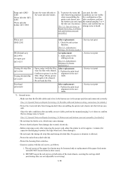
...notes: - Do not drop the ferrite core, which may be loosened only at 2 locations). ii. DO NOT loosen the red screws on Repair Servicing, (3) Printer unit and bottom case unit assembly, for details.] - Make sure that no grease is on strange noise is allowed. - Exercise caution with ink... manual purging 3 or 4 the tube (at replacement of the main chassis, securing the carriage shaft positioning (they are not visible. Repair Servicing, (3) Printer unit and bottom case unit assembly.] Platen unit QM2-2202 PR lift shaft ass'y QL2-0936 CL input gear QC1-6213 Timing slit ...
...notes: - Do not drop the ferrite core, which may be loosened only at 2 locations). ii. DO NOT loosen the red screws on Repair Servicing, (3) Printer unit and bottom case unit assembly, for details.] - Make sure that no grease is on strange noise is allowed. - Exercise caution with ink... manual purging 3 or 4 the tube (at replacement of the main chassis, securing the carriage shaft positioning (they are not visible. Repair Servicing, (3) Printer unit and bottom case unit assembly.] Platen unit QM2-2202 PR lift shaft ass'y QL2-0936 CL input gear QC1-6213 Timing slit ...

Service Manual
Page 20
V V V 1-15 3-2. Special Notes on Repair Servicing (1) External cover removal (I) Release the 2 hooks on the rear side of the printer (indicated by the blue circles). (II) Release the hooks on the left and right side of the main case (indicated by the blue circle). (III) While inserting the flat-blade screwdriver in the slots on the left and right sides of the printer front shown in the figures below, release the hooks to remove the main case from the bottom case.
V V V 1-15 3-2. Special Notes on Repair Servicing (1) External cover removal (I) Release the 2 hooks on the rear side of the printer (indicated by the blue circles). (II) Release the hooks on the left and right side of the main case (indicated by the blue circle). (III) While inserting the flat-blade screwdriver in the slots on the left and right sides of the printer front shown in the figures below, release the hooks to remove the main case from the bottom case.

Service Manual
Page 30
6 times Green (Power) Asia Supported 7 times Orange (Alarm) China Supported 8 times Green (Power) Taiwan Supported 9 times Orange (Alarm) Return to the menu selection Note: After setting the destination, confirm the model name and destination in service test print or EEPROM information print. [See 3.4. Verification Items, (1) Service test print, or (2) EEPROM information print.] To the top 1-25
6 times Green (Power) Asia Supported 7 times Orange (Alarm) China Supported 8 times Green (Power) Taiwan Supported 9 times Orange (Alarm) Return to the menu selection Note: After setting the destination, confirm the model name and destination in service test print or EEPROM information print. [See 3.4. Verification Items, (1) Service test print, or (2) EEPROM information print.] To the top 1-25
Service Manual
Page 33
...BK, Y, M, M2, C, C2) To the top 1-28 Cleaning time (BK/CL) 10. Print head temperature (BK/CL) 31. Operator call/service call error record 7. Longest period where printing stops 20. L & 4x6 print pages 26. Inside temperature 32. WP=0024 CDIN(LG=001 PB=000)...back side, U-turn front side, U-turn cassette feed pages (total, plain paper, High Resolution Paper & Matte Photo Paper, Photo Paper Pro & Photo Paper Plus Glossy & Photo Paper Plus Semi-gloss, Glossy Photo Paper, postcard, envelope) 22. Line inspection information HDEEPROM 33. Serial number 35. Lot number 36.
...BK, Y, M, M2, C, C2) To the top 1-28 Cleaning time (BK/CL) 10. Print head temperature (BK/CL) 31. Operator call/service call error record 7. Longest period where printing stops 20. L & 4x6 print pages 26. Inside temperature 32. WP=0024 CDIN(LG=001 PB=000)...back side, U-turn front side, U-turn cassette feed pages (total, plain paper, High Resolution Paper & Matte Photo Paper, Photo Paper Pro & Photo Paper Plus Glossy & Photo Paper Plus Semi-gloss, Glossy Photo Paper, postcard, envelope) 22. Line inspection information HDEEPROM 33. Serial number 35. Lot number 36.

Service Manual
Page 34
... describes the procedures for transporting the printer for returning after repair, etc. 1) In the service mode, press the Power button to... finish the mode, and confirm that the paper lifting plate of the sheet feeder unit is raised. 2) Keep the print head and ink tanks installed in the carriage. [See Caution 1 below.] 3) Turn off the printer... removed from damage due to dry. Memo: If the print head must be removed from the printer and transported alone, perform the following: (1) Attach the protective cap (used when the packing was...
... describes the procedures for transporting the printer for returning after repair, etc. 1) In the service mode, press the Power button to... finish the mode, and confirm that the paper lifting plate of the sheet feeder unit is raised. 2) Keep the print head and ink tanks installed in the carriage. [See Caution 1 below.] 3) Turn off the printer... removed from damage due to dry. Memo: If the print head must be removed from the printer and transported alone, perform the following: (1) Attach the protective cap (used when the packing was...


