Service Manual
Page 4
...implemented regulations for Chinese products MANUFACTURED: DEC 1999 U KYOWA PLASTIC IND. (SHENZHEN) CO., LTD. These regulations apply to laser products manufactured from the machine during any phase of user operation. The label shown below indicates compliance with FDA radiation performance ... Health and Human Services (DHHS) Radiation Performance Standard according to laser products marketed in the United States. Compliance is completely confined within the protective housings and external covers, the laser beam cannot escape from August 1, 1976. Since radiation emitted inside...
...implemented regulations for Chinese products MANUFACTURED: DEC 1999 U KYOWA PLASTIC IND. (SHENZHEN) CO., LTD. These regulations apply to laser products manufactured from the machine during any phase of user operation. The label shown below indicates compliance with FDA radiation performance ... Health and Human Services (DHHS) Radiation Performance Standard according to laser products marketed in the United States. Compliance is completely confined within the protective housings and external covers, the laser beam cannot escape from August 1, 1976. Since radiation emitted inside...

Service Manual
Page 19
OVERVIEW ...III-1 2. THEORY OF OPERATION CONTENTS 1. CONTROL ELECTRONICS III-10 3.1 Configuration...III-10 MECHANISMS ...III-2 2.1 Scanner Mechanism III-3 2.1.1 Document feeding and ejecting mechanism III-3 2.1.2 Scanner...III-3 2.2 Laser Printing Mechanism III-4 2.2.1 Paper pulling-in, registration, feeding, and ejecting mechanism III-4 2.2.2 Print process mechanism III-6 2.2.3 Heat-fixing mechanism III-7 2.3 Sensors and Actuators III-8 3. CHAPTER III.
OVERVIEW ...III-1 2. THEORY OF OPERATION CONTENTS 1. CONTROL ELECTRONICS III-10 3.1 Configuration...III-10 MECHANISMS ...III-2 2.1 Scanner Mechanism III-3 2.1.1 Document feeding and ejecting mechanism III-3 2.1.2 Scanner...III-3 2.2 Laser Printing Mechanism III-4 2.2.1 Paper pulling-in, registration, feeding, and ejecting mechanism III-4 2.2.2 Print process mechanism III-6 2.2.3 Heat-fixing mechanism III-7 2.3 Sensors and Actuators III-8 3. CHAPTER III.

Service Manual
Page 21
... MECHANISM - Paper pulling-in and registration mechanism Paper ejecting mechanism Heat-fixing mechanism Print process mechanism With paper feeding mechanism LASER PRINTING MECHANISM III - 2 Print process mechanism (consisting of charging, exposing, developing, transferring, and erasing processes) - Heat-fixing mechanism SENSORS AND ACTUATORS Document feeding and ejecting ...
... MECHANISM - Paper pulling-in and registration mechanism Paper ejecting mechanism Heat-fixing mechanism Print process mechanism With paper feeding mechanism LASER PRINTING MECHANISM III - 2 Print process mechanism (consisting of charging, exposing, developing, transferring, and erasing processes) - Heat-fixing mechanism SENSORS AND ACTUATORS Document feeding and ejecting ...

Service Manual
Page 25
2.2.2 Print process mechanism The print process unit works with laser beam, electrical charges, and toner. III - 6 The graph below shows the transition of electrical charge on the surface of the laser-sensitive drum through the five processes: charging, exposing, developing, transferring, and erasing processes.
2.2.2 Print process mechanism The print process unit works with laser beam, electrical charges, and toner. III - 6 The graph below shows the transition of electrical charge on the surface of the laser-sensitive drum through the five processes: charging, exposing, developing, transferring, and erasing processes.

Service Manual
Page 31
... models except FAX8060P/MFC9060) Side Cover (for FAX8060P/MFC9060 IV-23 1.10 Heat-fixing Unit, FU Lamp, and Paper Ejection Sensor Actuator IV-25 1.11 Laser Unit and Toner Sensor PCB IV-27 1.12 Bottom Plate ...IV-28 1.13 Low-voltage Power Supply PCB IV-30 1.14 Main PCB ...IV-31...
... models except FAX8060P/MFC9060) Side Cover (for FAX8060P/MFC9060 IV-23 1.10 Heat-fixing Unit, FU Lamp, and Paper Ejection Sensor Actuator IV-25 1.11 Laser Unit and Toner Sensor PCB IV-27 1.12 Bottom Plate ...IV-28 1.13 Low-voltage Power Supply PCB IV-30 1.14 Main PCB ...IV-31...
Service Manual
Page 33
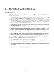
... problems by mishandling, observe the following precautions during maintenance work. (1) Unplug the power cord from the power outlet. (2) When servicing the optical system of the laser printing unit, be careful not to place screwdrivers or other heat-generating tools, take off any personal accessories such as aluminum foil. (9) Be sure to... in conductive sheets such as wrist watches and rings before replacing parts or units. IV - 1 DISASSEMBLY/REASSEMBLY Safety Precautions To prevent the creation of the laser beam.
... problems by mishandling, observe the following precautions during maintenance work. (1) Unplug the power cord from the power outlet. (2) When servicing the optical system of the laser printing unit, be careful not to place screwdrivers or other heat-generating tools, take off any personal accessories such as aluminum foil. (9) Be sure to... in conductive sheets such as wrist watches and rings before replacing parts or units. IV - 1 DISASSEMBLY/REASSEMBLY Safety Precautions To prevent the creation of the laser beam.

Service Manual
Page 34
... 2 Hinges on top cover Taptite, bind B M4x12 4 Hinges on main cover Taptite, cup B M4x12 4 Handset mount Taptite, cup B M3x10 2 Heat-fixing unit Taptite, bind B M4x12 1 Laser unit Toner sensor PCB Taptite, bind B M4x12 3 Taptite, cup B M3x8 1 Bottom plate AC grounding wire Interface connector Taptite, bind B M4x12 7 Taptite, cup S M3x6 3 Screw, pan...
... 2 Hinges on top cover Taptite, bind B M4x12 4 Hinges on main cover Taptite, cup B M4x12 4 Handset mount Taptite, cup B M3x10 2 Heat-fixing unit Taptite, bind B M4x12 1 Laser unit Toner sensor PCB Taptite, bind B M4x12 3 Taptite, cup B M3x8 1 Bottom plate AC grounding wire Interface connector Taptite, bind B M4x12 7 Taptite, cup S M3x6 3 Screw, pan...

Service Manual
Page 59
...from the toner sensor PCB. (2) Slightly lift up the toner sensor PCB and disconnect its harness. (3) Remove the three screws from the laser unit. (4) Slightly lift up the laser unit and disconnect the following from the main PCB: - NOTE: On the small PCB at the right side of the unit, glass,... or mirror. Laser diode harness (5-pin) - Reassembling Notes • Before putting the laser unit back into place, check for the adjustment in the factory. Polygon motor flat cable NOTE: When handling the...
...from the toner sensor PCB. (2) Slightly lift up the toner sensor PCB and disconnect its harness. (3) Remove the three screws from the laser unit. (4) Slightly lift up the laser unit and disconnect the following from the main PCB: - NOTE: On the small PCB at the right side of the unit, glass,... or mirror. Laser diode harness (5-pin) - Reassembling Notes • Before putting the laser unit back into place, check for the adjustment in the factory. Polygon motor flat cable NOTE: When handling the...

Service Manual
Page 63
... PCB and disconnect it from the low-voltage power supply PCB. (3) Disconnect the following harnesses from the main PCB: • Speaker harness (2-pin, P7) • Laser diode harness (5-pin, P6) • Toner sensor harness (4-pin, P5) • Polygon motor flat cable (5-pin, P4) • NCU harness 2*1 (6-pin, P13) • NCU harness...
... PCB and disconnect it from the low-voltage power supply PCB. (3) Disconnect the following harnesses from the main PCB: • Speaker harness (2-pin, P7) • Laser diode harness (5-pin, P6) • Toner sensor harness (4-pin, P5) • Polygon motor flat cable (5-pin, P4) • NCU harness 2*1 (6-pin, P13) • NCU harness...

Service Manual
Page 123
... 130 ms 1: 90 ms 0: No 1: Yes Selector 2: Default reduction rate for failure of the laser-sensitive drum in the laser unit will interpret the short-OFF as OFF. According to "0," the equipment records one -page data sent from the control panel. V - 43 This selector sets the minimum OFF duration ...automatic reduction during recording This selector sets the default reduction rate to be applied if the automatic reduction function fails to record one -page data at the size* specified according to select the desired paper size from the calling station in distinctive ringing. Default...
... 130 ms 1: 90 ms 0: No 1: Yes Selector 2: Default reduction rate for failure of the laser-sensitive drum in the laser unit will interpret the short-OFF as OFF. According to "0," the equipment records one -page data sent from the control panel. V - 43 This selector sets the minimum OFF duration ...automatic reduction during recording This selector sets the default reduction rate to be applied if the automatic reduction function fails to record one -page data at the size* specified according to select the desired paper size from the calling station in distinctive ringing. Default...

Service Manual
Page 143
... 4 Refer to scan. ) Document not detected by the document rear sensor. ) 50% or more faulty of white level data. ) One-line feeding time-out error. ) One-line scanning time-out error. ) Abnormal scanning reference voltage. ) Less than 50% faulty of white level data. ) Error codes in parentheses...72 ( 73 ( 74 ( 75 ( 76 ( 77 ( 78 ( 79 ( 80 ( 82 ( 83 ( 84 ( 88 ( A1 ( A2 ( A3 ( A4 ( A7 ( A8 ( A9 ( AC Error factor Laser scanner motor does not lock. ) Cannot detect Beam Detect signal. ) No toner cartridge loaded. ) Toner empty. ) In-house temperature error. ) Fixing heater harness disconnected or...
... 4 Refer to scan. ) Document not detected by the document rear sensor. ) 50% or more faulty of white level data. ) One-line feeding time-out error. ) One-line scanning time-out error. ) Abnormal scanning reference voltage. ) Less than 50% faulty of white level data. ) Error codes in parentheses...72 ( 73 ( 74 ( 75 ( 76 ( 77 ( 78 ( 79 ( 80 ( 82 ( 83 ( 84 ( 88 ( A1 ( A2 ( A3 ( A4 ( A7 ( A8 ( A9 ( AC Error factor Laser scanner motor does not lock. ) Cannot detect Beam Detect signal. ) No toner cartridge loaded. ) Toner empty. ) In-house temperature error. ) Fixing heater harness disconnected or...

Service Manual
Page 155
... drum unit, main cover, and high-voltage power supply PCB. (Contacts and in the illustration given on page VI-21) Check the connection of the laser diode harness on page VI21) Check the connection of the main-high-voltage flat cable. Main PCB At the printer side Clean the high-voltage...
... drum unit, main cover, and high-voltage power supply PCB. (Contacts and in the illustration given on page VI-21) Check the connection of the laser diode harness on page VI21) Check the connection of the main-high-voltage flat cable. Main PCB At the printer side Clean the high-voltage...

Service Manual
Page 158
... is secured with the screws without looseness. Check the connection of the polygon motor flat cable on the multi-purpose sheet feeder. Replace the laser unit. Main PCB At the scanner Check the following components: - VI - 19 Error code displayed. (Refer to use the recommended types of paper. Separator roller ...
... is secured with the screws without looseness. Check the connection of the polygon motor flat cable on the multi-purpose sheet feeder. Replace the laser unit. Main PCB At the scanner Check the following components: - VI - 19 Error code displayed. (Refer to use the recommended types of paper. Separator roller ...


