
Users Manual - English
Page 3
...below. Caution Use water or neutral detergents for cleaning. Do not use the printer safely After you have just used the printer, some parts inside the printer. There are high voltage electrodes inside the printer will damage the printer and the toner cartridge. Cleaning with wet hands - They will be extremely ...hot. Before you clean the printer, clear a paper jam or replace parts, make sure you have turned off the power switch and unplugged the printer from the AC power outlet. it might give you open the front or back ...
...below. Caution Use water or neutral detergents for cleaning. Do not use the printer safely After you have just used the printer, some parts inside the printer. There are high voltage electrodes inside the printer will damage the printer and the toner cartridge. Cleaning with wet hands - They will be extremely ...hot. Before you clean the printer, clear a paper jam or replace parts, make sure you have turned off the power switch and unplugged the printer from the AC power outlet. it might give you open the front or back ...
Users Manual - English
Page 8
..., that the products Product name: Model number: Product options: Laser Printer HL-5030, 5040, 5050 and HL-5070N HL-50 Lower Tray Unit LT-5000, DIMM complies with Part 15 of the following two conditions: (1) This device may not... cause harmful interference, and (2) this equipment does cause harmful interference to radio or television reception, which the receiver is encouraged to try to Part 15 of Conformity (For USA) Responsible Party: Brother International...
..., that the products Product name: Model number: Product options: Laser Printer HL-5030, 5040, 5050 and HL-5070N HL-50 Lower Tray Unit LT-5000, DIMM complies with Part 15 of the following two conditions: (1) This device may not... cause harmful interference, and (2) this equipment does cause harmful interference to radio or television reception, which the receiver is encouraged to try to Part 15 of Conformity (For USA) Responsible Party: Brother International...

Users Manual - English
Page 11
...(220 to 240 volt model only) This printer is a Class 1 laser product as defined in the scanner unit. CLASS 1LASERP RODUCT APPAREIL Å LASER DE CLASSE 1 LASER KLASSE 1 PRODUKT This printer has a Class 3B laser diode which produces invisible laser radiation in IEC 60825 specifications. You should... 1 ylittävälle näkymättömälle lasersäteilylle. Internal laser radiation Maximum radiation power: Wave length: Laser class: 5 mW 760 - 810 nm Class IIIb (Accordance with 21 CFR Part 1040.10) Class 3B (Accordance with IEC 60825) X Caution: Use...
...(220 to 240 volt model only) This printer is a Class 1 laser product as defined in the scanner unit. CLASS 1LASERP RODUCT APPAREIL Å LASER DE CLASSE 1 LASER KLASSE 1 PRODUKT This printer has a Class 3B laser diode which produces invisible laser radiation in IEC 60825 specifications. You should... 1 ylittävälle näkymättömälle lasersäteilylle. Internal laser radiation Maximum radiation power: Wave length: Laser class: 5 mW 760 - 810 nm Class IIIb (Accordance with 21 CFR Part 1040.10) Class 3B (Accordance with IEC 60825) X Caution: Use...
Users Manual - English
Page 17
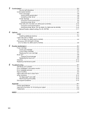
... ...3-8 Using control panel button 3-8 Using the printer driver ...3-8 Printer Settings ...3-9 Using the control panel button 3-9 Using the printer driver ...3-9 Print fonts (For HL-5040, HL-5050 and HL-5070N 3-10 Using the control panel button 3-10 Using the printer driver (For HL-5040, HL-5050 and HL-5070N 3-10 Network factory default setting (For HL-5070N 3-11 4 Options ...4-1 DIMM ...4-1 Installing additional...
... ...3-8 Using control panel button 3-8 Using the printer driver ...3-8 Printer Settings ...3-9 Using the control panel button 3-9 Using the printer driver ...3-9 Print fonts (For HL-5040, HL-5050 and HL-5070N 3-10 Using the control panel button 3-10 Using the printer driver (For HL-5040, HL-5050 and HL-5070N 3-10 Network factory default setting (For HL-5070N 3-11 4 Options ...4-1 DIMM ...4-1 Installing additional...

Users Manual - English
Page 18
...parts. 1 1 Printer 2 Drum Unit Assembly (with Toner Cartridge included) 3 Quick Setup Guide 4 CD-ROM 2 5 AC Power Cord Components may differ from one country to another. 3 4 5 The power cord may be IEEE 1284-compliant. ■ It is recommended to the iMac's keyboard. ■ The HL-5030... only supports the USB interface. ABOUT THIS PRINTER 1 - 1 Interface cable ■ An interface cable is in . 1 About this printer What is not a standard accessory. ■ Some computers have a USB and a ...
...parts. 1 1 Printer 2 Drum Unit Assembly (with Toner Cartridge included) 3 Quick Setup Guide 4 CD-ROM 2 5 AC Power Cord Components may differ from one country to another. 3 4 5 The power cord may be IEEE 1284-compliant. ■ It is recommended to the iMac's keyboard. ■ The HL-5030... only supports the USB interface. ABOUT THIS PRINTER 1 - 1 Interface cable ■ An interface cable is in . 1 About this printer What is not a standard accessory. ■ Some computers have a USB and a ...
Users Manual - English
Page 99
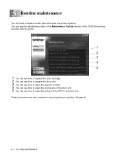
... the print quality in the drum unit. 5 Routine maintenance You will need to clean the surface of the CD-ROM we have provided with the printer. 1 2 3 4 5 1 You can see how to replace the toner cartridge. 2 You can see how to replace the drum unit. 3 You can see how to clean the... scanner window. 4 You can see how to clean the corona wire in the drum unit. 5 You can see how to replace certain parts and clean the printer regularly. You can see the maintenance video in the Maintenance Tutorial section of the OPC in Chapter 6. 5 - 1 ROUTINE MAINTENANCE
... the print quality in the drum unit. 5 Routine maintenance You will need to clean the surface of the CD-ROM we have provided with the printer. 1 2 3 4 5 1 You can see how to replace the toner cartridge. 2 You can see how to replace the drum unit. 3 You can see how to clean the... scanner window. 4 You can see how to clean the corona wire in the drum unit. 5 You can see how to replace certain parts and clean the printer regularly. You can see the maintenance video in the Maintenance Tutorial section of the OPC in Chapter 6. 5 - 1 ROUTINE MAINTENANCE
Users Manual - English
Page 104
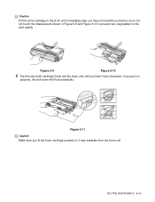
Caution Put the toner cartridge in the drum unit immediately after you put it may separate from the drum unit. If you have removed the protective cover. Figure 5-11 Caution Make sure you hear it lock into the drum unit until you fit the toner cartridge properly or it in Figure 5-9 and Figure 5-10 to prevent any degradation to the print quality. Do not touch the shaded parts shown in properly, the lock lever will lift automatically. ROUTINE MAINTENANCE 5 - 6 Figure 5-9 Figure 5-10 6 Put the new toner cartridge firmly into place.
Caution Put the toner cartridge in the drum unit immediately after you put it may separate from the drum unit. If you have removed the protective cover. Figure 5-11 Caution Make sure you hear it lock into the drum unit until you fit the toner cartridge properly or it in Figure 5-9 and Figure 5-10 to prevent any degradation to the print quality. Do not touch the shaded parts shown in properly, the lock lever will lift automatically. ROUTINE MAINTENANCE 5 - 6 Figure 5-9 Figure 5-10 6 Put the new toner cartridge firmly into place.
Users Manual - English
Page 111
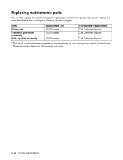
... may vary depending on 5% coverage per page. 5 - 13 ROUTINE MAINTENANCE These figures are based on your average type of pages. Replacing maintenance parts You need to replace the maintenance parts regularly to maintain print quality. You should replace the units listed below after printing the following number of print job and paper.
... may vary depending on 5% coverage per page. 5 - 13 ROUTINE MAINTENANCE These figures are based on your average type of pages. Replacing maintenance parts You need to replace the maintenance parts regularly to maintain print quality. You should replace the units listed below after printing the following number of print job and paper.

Users Manual - English
Page 112
6 Troubleshooting Identifying your problem First, check the following: ■ The power plug is connected properly and the printer is turned on. ■ All of the protective parts have been removed. ■ The toner cartridge and drum unit are problems with the above checks, please find your problem with : Print quality See Improving ...
6 Troubleshooting Identifying your problem First, check the following: ■ The power plug is connected properly and the printer is turned on. ■ All of the protective parts have been removed. ■ The toner cartridge and drum unit are problems with the above checks, please find your problem with : Print quality See Improving ...
Users Manual - English
Page 116
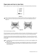
... not start printing, please check that all paper from the paper tray and straighten the stack when you have just used the printer, some parts inside the printer are extremely hot. Toner Drum Paper Status Figure 6-1 After you add new paper. Clear the jammed paper as shown below. Paper ...all the remaining jammed paper has been removed from feeding through the printer at one time and reduces paper jams. TROUBLESHOOTING 6 - 5 When you open the front cover or back output tray of the printer, never touch the shaded parts shown in the following steps, you can install the paper tray ...
... not start printing, please check that all paper from the paper tray and straighten the stack when you have just used the printer, some parts inside the printer are extremely hot. Toner Drum Paper Status Figure 6-1 After you add new paper. Clear the jammed paper as shown below. Paper ...all the remaining jammed paper has been removed from feeding through the printer at one time and reduces paper jams. TROUBLESHOOTING 6 - 5 When you open the front cover or back output tray of the printer, never touch the shaded parts shown in the following steps, you can install the paper tray ...
Users Manual - English
Page 119
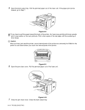
Figure 6-8 If you have just used the printer, some internal parts of the printer, the fuser may get dirty with toner powder and it may scatter on the next printouts. Close the back output tray. 6 - 8 TROUBLESHOOTING Figure 6-9 6 Open the ... stops. 5 Open the back output tray. Print a few copies of the test page until the scattering of the fuser unit. Caution After you touch the internal parts of the fuser unit. Wait for the printer to Step 7. Figure 6-10 7 Close the jam clear cover. Pull the jammed paper out of the...
Figure 6-8 If you have just used the printer, some internal parts of the printer, the fuser may get dirty with toner powder and it may scatter on the next printouts. Close the back output tray. 6 - 8 TROUBLESHOOTING Figure 6-9 6 Open the ... stops. 5 Open the back output tray. Print a few copies of the test page until the scattering of the fuser unit. Caution After you touch the internal parts of the fuser unit. Wait for the printer to Step 7. Figure 6-10 7 Close the jam clear cover. Pull the jammed paper out of the...

Service Manual
Page 2
..., Ltd. Hewlett Packard is a registered trademark and HP LaserJet is a registered trademark of Hewlett Packard Company. © Copyright Brother Industries, Ltd. 2003 All rights reserved. Windows is a trademark of Microsoft Corporation. No part of International Business Machines Corporation. and other countries, and TrueType is a registered trademark of Seiko Epson Corporation. Specifications are registered...
..., Ltd. Hewlett Packard is a registered trademark and HP LaserJet is a registered trademark of Hewlett Packard Company. © Copyright Brother Industries, Ltd. 2003 All rights reserved. Windows is a trademark of Microsoft Corporation. No part of International Business Machines Corporation. and other countries, and TrueType is a registered trademark of Seiko Epson Corporation. Specifications are registered...
Service Manual
Page 3
... is subject to change due to maintain the high printing quality and performance of this machine" or "the printer"). HL-5030/5040/5050/5070N SERVICE MANUAL PREFACE This service manual contains basic information required for disassembling and re-assembling the ...chapters: CHAPTER 1: GENERAL Features, specifications, etc. CHAPTER 5: PERIODIC MAINTENANCE Periodical replacements parts, consumable parts, etc. CHAPTER 4: DISASSEMBLY AND RE-ASSEMBLY Procedures for after-sales service of the laser printer (hereinafter referred to find the cause of the mechanical system, the electrical system ...
... is subject to change due to maintain the high printing quality and performance of this machine" or "the printer"). HL-5030/5040/5050/5070N SERVICE MANUAL PREFACE This service manual contains basic information required for disassembling and re-assembling the ...chapters: CHAPTER 1: GENERAL Features, specifications, etc. CHAPTER 5: PERIODIC MAINTENANCE Periodical replacements parts, consumable parts, etc. CHAPTER 4: DISASSEMBLY AND RE-ASSEMBLY Procedures for after-sales service of the laser printer (hereinafter referred to find the cause of the mechanical system, the electrical system ...

Service Manual
Page 7
... 6-6 3.2 Error Message Printouts 6-7 4. INCORRECT PRINTOUT 6-45 9. PERIODICAL REPLACEMENT PARTS 5-8 2.1 Fixing Unit ...5-9 2.2 Paper Feeding Kit...5-12 3. PERIODICAL CLEANING 5-14 3.1 Cleaning the Printer Exterior 5-14 3.2 Cleaning the Drum Unit 5-14 3.3 Cleaning the Scanner Window...7.4 Location of Grounding Contacts 6-44 7.4.1 Drum unit ...6-44 7.4.2 Printer body & Paper cassette 6-44 8. MALFUNCTIONS 6-19 7. HL-5030/5040/5050/5070N SERVICE MANUAL 5. SOFTWARE SETTING PROBLEMS 6-16 6. CONSUMABLE PARTS 5-1 1.1 Drum Unit...5-1 1.2 Toner Cartridge...5-3 2. MTBF / MTTR...
... 6-6 3.2 Error Message Printouts 6-7 4. INCORRECT PRINTOUT 6-45 9. PERIODICAL REPLACEMENT PARTS 5-8 2.1 Fixing Unit ...5-9 2.2 Paper Feeding Kit...5-12 3. PERIODICAL CLEANING 5-14 3.1 Cleaning the Printer Exterior 5-14 3.2 Cleaning the Drum Unit 5-14 3.3 Cleaning the Scanner Window...7.4 Location of Grounding Contacts 6-44 7.4.1 Drum unit ...6-44 7.4.2 Printer body & Paper cassette 6-44 8. MALFUNCTIONS 6-19 7. HL-5030/5040/5050/5070N SERVICE MANUAL 5. SOFTWARE SETTING PROBLEMS 6-16 6. CONSUMABLE PARTS 5-1 1.1 Drum Unit...5-1 1.2 Toner Cartridge...5-3 2. MTBF / MTTR...

Service Manual
Page 12
... power switch and unplug the power cord from the power outlet before accessing any parts inside the printer are used . NOTE: Indicates notes and useful tips to prevent possible personal injury. ! WARNING Some parts inside the printer, never touch the shaded parts shown in this service manual: WARNING Indicates warnings that must be exercised even...
... power switch and unplug the power cord from the power outlet before accessing any parts inside the printer are used . NOTE: Indicates notes and useful tips to prevent possible personal injury. ! WARNING Some parts inside the printer, never touch the shaded parts shown in this service manual: WARNING Indicates warnings that must be exercised even...

Service Manual
Page 30
... (2) Process unit: Imprinted on the rear of the printer and printer parts: < ID for production month > A: January B: E: May F: J: September K: February June October < ID for year > 2: 2002 3: 2003 C: March G: July L: November D: April H: August M: December < ID for factory > 9: Kariya Plant A: J: Buji Nan Ling Factory Mie Brother C: BIUK (1) Printer: Printed on the label attached on the aluminum bag...
... (2) Process unit: Imprinted on the rear of the printer and printer parts: < ID for production month > A: January B: E: May F: J: September K: February June October < ID for year > 2: 2002 3: 2003 C: March G: July L: November D: April H: August M: December < ID for factory > 9: Kariya Plant A: J: Buji Nan Ling Factory Mie Brother C: BIUK (1) Printer: Printed on the label attached on the aluminum bag...

Service Manual
Page 36
HL-5030/5040/5050/5070N SERVICE MANUAL 3.1.1 Install the drum unit assembly (1) Open the front cover by pressing the front cover release button. (2) Unpack the drum unit assembly. Check that they locate correctly into the printer. Fig. 2-3 (5) Close the front cover of the printer. 3.1.2 Load paper into the ... 13 in. Remove the protective part. (3) Rock it from side to side several times to fit the paper size. Fig. 2-2 (4) Put the drum unit assembly into the slots. paper, press the universal guide release lever to extend the rear of the printer. (2) While pressing the paper ...
HL-5030/5040/5050/5070N SERVICE MANUAL 3.1.1 Install the drum unit assembly (1) Open the front cover by pressing the front cover release button. (2) Unpack the drum unit assembly. Check that they locate correctly into the printer. Fig. 2-3 (5) Close the front cover of the printer. 3.1.2 Load paper into the ... 13 in. Remove the protective part. (3) Rock it from side to side several times to fit the paper size. Fig. 2-2 (4) Put the drum unit assembly into the slots. paper, press the universal guide release lever to extend the rear of the printer. (2) While pressing the paper ...

Service Manual
Page 68
... because the paper path will be fed from the service manual information for printers shipped to Europe as follows: (1) The paper cassette supplied with the HL- 5030/5040/5050/5070N printer does not have a paper path. (2) The paper cassette supplied with the LT-5000 unit, and install the standard cassette... to the lower tray. Failure to do so will cause paper jams as the paper cannot be blocked. (4) For paper cassettes supplied as spare parts,...
... because the paper path will be fed from the service manual information for printers shipped to Europe as follows: (1) The paper cassette supplied with the HL- 5030/5040/5050/5070N printer does not have a paper path. (2) The paper cassette supplied with the LT-5000 unit, and install the standard cassette... to the lower tray. Failure to do so will cause paper jams as the paper cannot be blocked. (4) For paper cassettes supplied as spare parts,...

Service Manual
Page 85
...Lower cassette sensor Lower paper exit sensor Lower cassette exit sensor Multi-purpose tray paper exit sensor HL-5030 HL-5040 HL-5050/5070N : Built-in : Not built-in this manual. The engine PCB controls the following parts by using the transferred signal data; • Main motor • Solenoid • Fan... paper exit sensor For the circuit diagram of the engine PCB, see APPENDIX 9. and 10. 'ENGINE PCB CIRCUIT DIAGRAM' in 3-17 HL-5030/5040/5050/5070N SERVICE MANUAL 1.4 Engine PCB The gate array which transforms the serial signal from the main PCB into the parallel signal is...
...Lower cassette sensor Lower paper exit sensor Lower cassette exit sensor Multi-purpose tray paper exit sensor HL-5030 HL-5040 HL-5050/5070N : Built-in : Not built-in this manual. The engine PCB controls the following parts by using the transferred signal data; • Main motor • Solenoid • Fan... paper exit sensor For the circuit diagram of the engine PCB, see APPENDIX 9. and 10. 'ENGINE PCB CIRCUIT DIAGRAM' in 3-17 HL-5030/5040/5050/5070N SERVICE MANUAL 1.4 Engine PCB The gate array which transforms the serial signal from the main PCB into the parallel signal is...

Service Manual
Page 98
...touch a metal portion of the equipment to discharge any parts inside the printer. (2) Some parts inside the printer, never touch the red colored parts shown in the following torque values. When opening the front cover or rear cover to access any parts inside the printer are functioning properly before accessing any static electricity charge on..., release the connector lock first to the gears and applicable positions specified in the correct protective packaging. (6) Be sure to the following figures. ! HL-5030/5040/5050/5070N SERVICE MANUAL CHAPTER 4 DISASSEMBLY AND RE-ASSEMBLY 1.
...touch a metal portion of the equipment to discharge any parts inside the printer. (2) Some parts inside the printer, never touch the red colored parts shown in the following torque values. When opening the front cover or rear cover to access any parts inside the printer are functioning properly before accessing any static electricity charge on..., release the connector lock first to the gears and applicable positions specified in the correct protective packaging. (6) Be sure to the following figures. ! HL-5030/5040/5050/5070N SERVICE MANUAL CHAPTER 4 DISASSEMBLY AND RE-ASSEMBLY 1.


