User Manual
Page 3
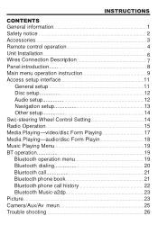
...Unit Installation 6 Wires Connection Description 7 Panel introduction 8 Main menu operation instruction 9 Access setup interface 11 General setup 11 Disc setup 12 Audio setup 12 Navigation setup 13 Other setup 14 Swc-steering Wheel Control Setting 14 Radio Operation 15 Media Playing-video/disc Form Playing 17 Media Playing-audio/disc Form Playin 18 Music Playing Menu 19 BT operation 19 Bluetooth operation menu 19 Bluetooth dialing 20 Bluetooth call 21 Bluetooth phone book 21 Bluetooth phone call history 22 Bluetooth Music-a2dp 23 Picture 23 Camera/Aux/Av meun 25 Trouble...
...Unit Installation 6 Wires Connection Description 7 Panel introduction 8 Main menu operation instruction 9 Access setup interface 11 General setup 11 Disc setup 12 Audio setup 12 Navigation setup 13 Other setup 14 Swc-steering Wheel Control Setting 14 Radio Operation 15 Media Playing-video/disc Form Playing 17 Media Playing-audio/disc Form Playin 18 Music Playing Menu 19 BT operation 19 Bluetooth operation menu 19 Bluetooth dialing 20 Bluetooth call 21 Bluetooth phone book 21 Bluetooth phone call history 22 Bluetooth Music-a2dp 23 Picture 23 Camera/Aux/Av meun 25 Trouble...
User Manual
Page 4
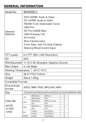
BN965BLC DVD ±R/RW Audio & Video CD ±R/RW Audio & Video FM/AM Tuner (Switchable Tuner) USB Port SD Port (64GB Max) USB Charging (1A) A/V In/Out Rear Camera Input Front, Rear, Sub Pre-Amp Outputs Steering Wheel Control Input 6.5 TFT (800 x 480 Resolution) 11-16 V DC Allowable, Negative Ground 4 x 80 Watts Compatible Formats Picture/Audio formats JPEG, BMP, PNG, MP3,AAC,WAV
BN965BLC DVD ±R/RW Audio & Video CD ±R/RW Audio & Video FM/AM Tuner (Switchable Tuner) USB Port SD Port (64GB Max) USB Charging (1A) A/V In/Out Rear Camera Input Front, Rear, Sub Pre-Amp Outputs Steering Wheel Control Input 6.5 TFT (800 x 480 Resolution) 11-16 V DC Allowable, Negative Ground 4 x 80 Watts Compatible Formats Picture/Audio formats JPEG, BMP, PNG, MP3,AAC,WAV
User Manual
Page 9
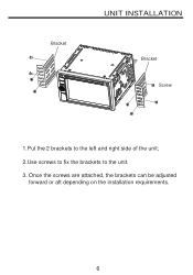
Once the screws are attached, the brackets can be adjusted forward or aft depending on the installation requirements. Bracket UNIT INSTALLATION Bracket Screw 1.Put the 2 brackets to the left and right side of the unit; 2.Use screws to fix the brackets to the unit. 3.
Once the screws are attached, the brackets can be adjusted forward or aft depending on the installation requirements. Bracket UNIT INSTALLATION Bracket Screw 1.Put the 2 brackets to the left and right side of the unit; 2.Use screws to fix the brackets to the unit. 3.
User Manual
Page 10
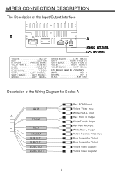
...BRAKE VIOLET/WHITE..........REVERSE BLUE ANT.CONT BLACK GROUND BLUE/WHITE P.CONT WHITE............LEFT FRONT(+) WHITE/BLACK......LEFT FRONT(-) GREEN LEFT REAR(+) GREEN/BLACK.......LEFT REAR(-) GREY............RIGHT FRONT(+) GREY/BLACK......RIGHT FRONT(-) VIOLET............RIGHT REAR(+) VIOLET/BLACK......RIGHT REAR(-) 4 5& & 3 */( 8)& & - $ 0/53 0- WIRES CONNECTION DESCRIPTION The Description of the Wiring Diagram for Socket A AV IN A FRONT REAR CAMERA SUB OUT SUB OUT VIDEO OUT 1 VIDEO OUT 2 Red RCA R Input Yellow Video Input White RCA L Input Red Front R Output White Front L Output Red...
...BRAKE VIOLET/WHITE..........REVERSE BLUE ANT.CONT BLACK GROUND BLUE/WHITE P.CONT WHITE............LEFT FRONT(+) WHITE/BLACK......LEFT FRONT(-) GREEN LEFT REAR(+) GREEN/BLACK.......LEFT REAR(-) GREY............RIGHT FRONT(+) GREY/BLACK......RIGHT FRONT(-) VIOLET............RIGHT REAR(+) VIOLET/BLACK......RIGHT REAR(-) 4 5& & 3 */( 8)& & - $ 0/53 0- WIRES CONNECTION DESCRIPTION The Description of the Wiring Diagram for Socket A AV IN A FRONT REAR CAMERA SUB OUT SUB OUT VIDEO OUT 1 VIDEO OUT 2 Red RCA R Input Yellow Video Input White RCA L Input Red Front R Output White Front L Output Red...


