Installation guide
Page 2
... B digital apparatus meets all of procedures other than those specified herein may be adjusted or repaired by anyone except properly qualified service personnel. Save your LIFESTYLE® media center and Acoustimass® module enclosures: The lightning flash with any local regulations. Liquids can cause a failure and/or a fire hazard. AVIS RISQUE...
... B digital apparatus meets all of procedures other than those specified herein may be adjusted or repaired by anyone except properly qualified service personnel. Save your LIFESTYLE® media center and Acoustimass® module enclosures: The lightning flash with any local regulations. Liquids can cause a failure and/or a fire hazard. AVIS RISQUE...

Installation guide
Page 3
System: (circle one) LIFESTYLE® 18 system LIFESTYLE® 28 system LIFESTYLE® 38 system LIFESTYLE® 48 system Media center serial number Acoustimass module serial number Dealer name Dealer phone Purchase date Be sure to fill out ... limited viewing uses only unless otherwise authorized by Macrovision Corporation. "Dolby" and the double-D symbol are registered trademarks of this guide. ©2004 Bose Corporation. Use of Digital Theater Systems, Inc. No part of Dolby Laboratories. All rights reserved. Manufactured under license from Dolby Laboratories. "DTS" ...
System: (circle one) LIFESTYLE® 18 system LIFESTYLE® 28 system LIFESTYLE® 38 system LIFESTYLE® 48 system Media center serial number Acoustimass module serial number Dealer name Dealer phone Purchase date Be sure to fill out ... limited viewing uses only unless otherwise authorized by Macrovision Corporation. "Dolby" and the double-D symbol are registered trademarks of this guide. ©2004 Bose Corporation. Use of Digital Theater Systems, Inc. No part of Dolby Laboratories. All rights reserved. Manufactured under license from Dolby Laboratories. "DTS" ...

Installation guide
Page 4
l E li h E i F Contents Where to add 32 How you begin 5 Special indicator used in this book 5 Unpacking 5 System Installation 6 Cables and accessories 7 Placing your speakers 8 Left and right front speaker placement 8 Center speaker placement 9 Surround speaker placement 10 Acoustimass® module placement 10 Placing your media center 11 Connecting the speakers to the Acoustimass module 12 Connecting the plug-in cable to Jewel Cube® speakers 12 Making the two-wire connections for cube or cube array speakers 13 Connecting the Acoustimass module to the media center...
l E li h E i F Contents Where to add 32 How you begin 5 Special indicator used in this book 5 Unpacking 5 System Installation 6 Cables and accessories 7 Placing your speakers 8 Left and right front speaker placement 8 Center speaker placement 9 Surround speaker placement 10 Acoustimass® module placement 10 Placing your media center 11 Connecting the speakers to the Acoustimass module 12 Connecting the plug-in cable to Jewel Cube® speakers 12 Making the two-wire connections for cube or cube array speakers 13 Connecting the Acoustimass module to the media center...
Installation guide
Page 5
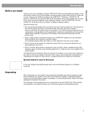
...identifies parts which will identify and connect the cables that are four different systems, the LIFESTYLE® 18 Series II, LIFESTYLE® 28 Series II, LIFESTYLE® 38, and the LIFESTYLE® 48 systems. All include multiple room connections, most include the AdaptiQ® audio calibration system... to other pieces of equipment, such as the center of a Bose® LIFESTYLE® DVD home entertainment system. If any connections. Unpacking After unpacking your authorized Bose dealer immediately, or contact Bose directly. Refer to see the on the next two pages will have...
...identifies parts which will identify and connect the cables that are four different systems, the LIFESTYLE® 18 Series II, LIFESTYLE® 28 Series II, LIFESTYLE® 38, and the LIFESTYLE® 48 systems. All include multiple room connections, most include the AdaptiQ® audio calibration system... to other pieces of equipment, such as the center of a Bose® LIFESTYLE® DVD home entertainment system. If any connections. Unpacking After unpacking your authorized Bose dealer immediately, or contact Bose directly. Refer to see the on the next two pages will have...
Installation guide
Page 6
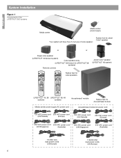
...Jewel Cube® speaker or or Single cube speaker (LIFESTYLE® 18 Series II system) Cube speaker array (LIFESTYLE® 28 Series II & LIFESTYLE® 38 systems) Remote controls Jewel Cube® speaker (LIFESTYLE® 48 system) On Off Mute All Mute CD·DVD...3 4 5 6 7 8 9 Info Last 0 uMusic Rating Similar Whole CD CD # Playlist Rubber feet for cube speakers LIFESTYLE® 18, 28 LIFESTYLE® 38, 48 systems systems Acoustimass® module Rubber feet for Acoustimass module Media center power supply AC power cord Acoustimass module AC power cord ...
...Jewel Cube® speaker or or Single cube speaker (LIFESTYLE® 18 Series II system) Cube speaker array (LIFESTYLE® 28 Series II & LIFESTYLE® 38 systems) Remote controls Jewel Cube® speaker (LIFESTYLE® 48 system) On Off Mute All Mute CD·DVD...3 4 5 6 7 8 9 Info Last 0 uMusic Rating Similar Whole CD CD # Playlist Rubber feet for cube speakers LIFESTYLE® 18, 28 LIFESTYLE® 38, 48 systems systems Acoustimass® module Rubber feet for Acoustimass module Media center power supply AC power cord Acoustimass module AC power cord ...
Installation guide
Page 7
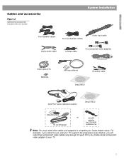
English Cables and accessories Figure 2 Cables and accessories included with your system System Installation L R Front speaker cables Surround speaker cables Audio input cable Stereo audio cable S-Video cable Two component video adapters FM antenna Video cable (6 ft) Batteries AM loop antenna IR emitter cable Setup disc 1 ADAPTiQ® audio calibration system Setup disc 2 Mounting strip TV on/off sensor or SCART adapter for 220-240V systems only Note: You may need three component video cables long enough to reach from your media center component video adapter to ...
English Cables and accessories Figure 2 Cables and accessories included with your system System Installation L R Front speaker cables Surround speaker cables Audio input cable Stereo audio cable S-Video cable Two component video adapters FM antenna Video cable (6 ft) Batteries AM loop antenna IR emitter cable Setup disc 1 ADAPTiQ® audio calibration system Setup disc 2 Mounting strip TV on/off sensor or SCART adapter for 220-240V systems only Note: You may need three component video cables long enough to reach from your media center component video adapter to ...
Installation guide
Page 8
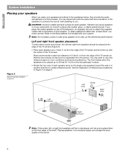
... place a cube or cube array speaker on its side, as this distance based on smooth surfaces like marble, glass, or highly polished wood. Bose recommends a maximum distance of 3 feet (1 m) from the picture. Left and right front speaker placement To best match sound and picture, the ...reflected sound. Placing speakers in an enclosed space can cause speakers to the bottom of the shelf. To obtain additional rubber feet, contact Bose® customer service. Figure 3 Recommended speaker locations Left front Center Right front Left surround Right surround Note: If the center, left...
... place a cube or cube array speaker on its side, as this distance based on smooth surfaces like marble, glass, or highly polished wood. Bose recommends a maximum distance of 3 feet (1 m) from the picture. Left and right front speaker placement To best match sound and picture, the ...reflected sound. Placing speakers in an enclosed space can cause speakers to the bottom of the shelf. To obtain additional rubber feet, contact Bose® customer service. Figure 3 Recommended speaker locations Left front Center Right front Left surround Right surround Note: If the center, left...
Installation guide
Page 9
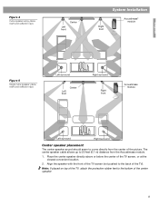
The center speaker cable allows up to 20 feet (6.1 m) distance from the center of the center speaker. 9 Figure 4 Cube speaker array placement and reflection rays Left front Center System Installation Right front Acoustimass® module English Figure 5 Single cube speaker placement and reflection rays Left surround Left front Center Right surround Right front Acoustimass module Left surround Right surround Center speaker placement The center speaker sound should seem to come directly from the Acoustimass module. 1. Align the speaker with the front of the TV screen (not ...
The center speaker cable allows up to 20 feet (6.1 m) distance from the center of the center speaker. 9 Figure 4 Cube speaker array placement and reflection rays Left front Center System Installation Right front Acoustimass® module English Figure 5 Single cube speaker placement and reflection rays Left surround Left front Center Right surround Right front Acoustimass module Left surround Right surround Center speaker placement The center speaker sound should seem to come directly from the Acoustimass module. 1. Align the speaker with the front of the TV screen (not ...
Installation guide
Page 10
... the listeners so that the grille with your room. Do not direct the sound straight at ear height (when seated) or higher, if possible. 2. Note: Bose offers a variety of sound around the listener. Move it there and in the space provided on the end the module, which provide ventilation for the... wall as the TV, or at the same end of the sound source. Place the speakers at the listener. To contact Bose, refer to the address sheet included with the Bose logo faces the room or is a good time to record it further if you may want to Figure 4). Follow these guidelines...
... the listeners so that the grille with your room. Do not direct the sound straight at ear height (when seated) or higher, if possible. 2. Note: Bose offers a variety of sound around the listener. Move it there and in the space provided on the end the module, which provide ventilation for the... wall as the TV, or at the same end of the sound source. Place the speakers at the listener. To contact Bose, refer to the address sheet included with the Bose logo faces the room or is a good time to record it further if you may want to Figure 4). Follow these guidelines...
Installation guide
Page 11
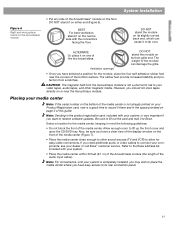
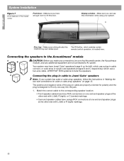
... number on the bottom of the media center is not already printed on the floor. Select a location for easy cable connections. Allow enough room to Bose. Note: For convenience, until your video tapes, audio tapes, and other sound sources (TV and VCR) to its rear connection panel. 11 Note: Sending ...curved back end, which can damage the grille. • Once you should not store tapes directly on the narrow side with your dealer or call Bose® customer service. If you want to tip over. BEST For best ventilation, stand it on or near the corners of the module can cause...
... number on the bottom of the media center is not already printed on the floor. Select a location for easy cable connections. Allow enough room to Bose. Note: For convenience, until your video tapes, audio tapes, and other sound sources (TV and VCR) to its rear connection panel. 11 Note: Sending ...curved back end, which can damage the grille. • Once you should not store tapes directly on the narrow side with your dealer or call Bose® customer service. If you want to tip over. BEST For best ventilation, stand it on or near the corners of the module can cause...
Installation guide
Page 12
... 7 Front features of the plug-in cable to Jewel Cube® speakers Note: If your system. ® Disc tray - Make sure nothing blocks this door. LIFESTYLE® DVD systems include five speakers. Make sure you can see this information while using your system has cube or cube array speakers, follow the...
... 7 Front features of the plug-in cable to Jewel Cube® speakers Note: If your system. ® Disc tray - Make sure nothing blocks this door. LIFESTYLE® DVD systems include five speakers. Make sure you can see this information while using your system has cube or cube array speakers, follow the...
Installation guide
Page 13
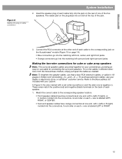
...the speaker plug of each speaker. 1. Note: To lengthen the speaker cables, use cable for your convenience, providing an easy-to the Bose address list included with L (left surround and right surround jacks. Match the correct cable to the corresponding speaker location. • Front ... cables as needed. A red collar on each + wire is positive (+) and the plain one end, with your dealer or electronics store, or call Bose® customer service. To run the cables in 18gauge or thicker cord (connecting + to -). These wires match the positive (red) and negative (black...
...the speaker plug of each speaker. 1. Note: To lengthen the speaker cables, use cable for your convenience, providing an easy-to the Bose address list included with L (left surround and right surround jacks. Match the correct cable to the corresponding speaker location. • Front ... cables as needed. A red collar on each + wire is positive (+) and the plain one end, with your dealer or electronics store, or call Bose® customer service. To run the cables in 18gauge or thicker cord (connecting + to -). These wires match the positive (red) and negative (black...
Installation guide
Page 14
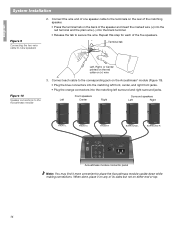
English System Installation Figure 9 Connecting the two-wire cable to the Acoustimass module 3. When done, place it more convenient to secure the wire. Terminal tab Left, Right, or Center printed on the red collar on the Acoustimass® module (Figure 10). • Plug the blue connectors into the matching left surround and right surround jacks. Connect each of the five speakers. Connect the wire end of one speaker cable to the terminals on the rear of the matching speaker. • Press the terminal tab on the back of its sides but not on any of the speaker and ...
English System Installation Figure 9 Connecting the two-wire cable to the Acoustimass module 3. When done, place it more convenient to secure the wire. Terminal tab Left, Right, or Center printed on the red collar on the Acoustimass® module (Figure 10). • Plug the blue connectors into the matching left surround and right surround jacks. Connect each of the five speakers. Connect the wire end of one speaker cable to the terminals on the rear of the matching speaker. • Press the terminal tab on the back of its sides but not on any of the speaker and ...
Installation guide
Page 15
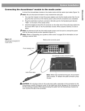
When properly inserted, it easier to the media center with the audio input cable (Figure 11). Figure 11 Acoustimass connection to the Acoustimass module. When disconnecting the cable from the Acoustimass module, be sure to press the tab on connecting a second room. be sure to unwrap the power cord for information on the connector. 15 CAUTION: Do not place strain on the audio input cable, especially on the other end of the media center. 3. You may cause damage to other end into the media center power cord; Insert the telephone-style RJ-45 connector on the ...
When properly inserted, it easier to the media center with the audio input cable (Figure 11). Figure 11 Acoustimass connection to the Acoustimass module. When disconnecting the cable from the Acoustimass module, be sure to press the tab on connecting a second room. be sure to unwrap the power cord for information on the connector. 15 CAUTION: Do not place strain on the audio input cable, especially on the other end of the media center. 3. You may cause damage to other end into the media center power cord; Insert the telephone-style RJ-45 connector on the ...

Installation guide
Page 16
Figure 12 Connections for the AM and FM antennas AM antenna lead FM dipole antenna lead Media center rear panel Note: The FM jack (75 ohm) can be adversely affected by the media center. CAUTION: Do not attempt to connect a television cable to your home. Note: AM radio reception may be used with the antenna. This connection is received by your television. Connecting the FM antenna Plug the connector on the back panel of the antenna arms to get optimum FM reception. Plug the connector on the base, following the instructions enclosed with the AM antenna. 3. Stand the loop ...
Figure 12 Connections for the AM and FM antennas AM antenna lead FM dipole antenna lead Media center rear panel Note: The FM jack (75 ohm) can be adversely affected by the media center. CAUTION: Do not attempt to connect a television cable to your home. Note: AM radio reception may be used with the antenna. This connection is received by your television. Connecting the FM antenna Plug the connector on the back panel of the antenna arms to get optimum FM reception. Plug the connector on the base, following the instructions enclosed with the AM antenna. 3. Stand the loop ...
Installation guide
Page 17
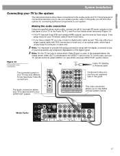
... later in this guide you to the media center and TV. In this guide This audio connection allows your TV to send sound to your LIFESTYLE® system This video connection allows you will allow you may look different. It may either be sure to use the ones for connecting additional... snap fit connector on your TV may connect a digital audio cable as well. In the example below show basic connections to view DVDs and see LIFESTYLE® system menus. Later in this case, use your TV remote control to select VIDEO 1 to the Audio IN TV L and R on the rear panel...
... later in this guide you to the media center and TV. In this guide This audio connection allows your TV to send sound to your LIFESTYLE® system This video connection allows you will allow you may look different. It may either be sure to use the ones for connecting additional... snap fit connector on your TV may connect a digital audio cable as well. In the example below show basic connections to view DVDs and see LIFESTYLE® system menus. Later in this case, use your TV remote control to select VIDEO 1 to the Audio IN TV L and R on the rear panel...
Installation guide
Page 18
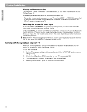
... your TV, such as VIDEO 1 or VIDEO 3, because that is the video input you must select, using your TV remote, to see a DVD picture or LIFESTYLE® system menus on your TV owner's guide for information on how to set to their sound off the speakers in your TV When you... listen to TV sound through your LIFESTYLE® system, the speakers in your TV may be called TV/VIDEO, Source, or Input. You may have a choice between Variable and Fixed, choose Fixed...
... your TV, such as VIDEO 1 or VIDEO 3, because that is the video input you must select, using your TV remote, to see a DVD picture or LIFESTYLE® system menus on your TV owner's guide for information on how to set to their sound off the speakers in your TV When you... listen to TV sound through your LIFESTYLE® system, the speakers in your TV may be called TV/VIDEO, Source, or Input. You may have a choice between Variable and Fixed, choose Fixed...
Installation guide
Page 19
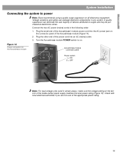
... Installation Connecting the system to on. A quality suppressor can damage electronic components in the following order: 1. Turn the Acoustimass module POWER switch to power Note: Bose recommends using a quality surge suppressor on the connector panel of the appropriate power rating. 19 Plug the small end of the Acoustimass® module power...
... Installation Connecting the system to on. A quality suppressor can damage electronic components in the following order: 1. Turn the Acoustimass module POWER switch to power Note: Bose recommends using a quality surge suppressor on the connector panel of the appropriate power rating. 19 Plug the small end of the Acoustimass® module power...
Installation guide
Page 20
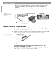
... back on the media center connection panel, do so now (Figure 15). 5. Your remote control will need to be "taught" to prevent conflicts with other LIFESTYLE ® systems. Figure 16 Remote control battery installation Four (4) AAA (IEC-LR3) batteries + ++ + Battery compartment cover Replace all four batteries when the remote control stops...
... back on the media center connection panel, do so now (Figure 15). 5. Your remote control will need to be "taught" to prevent conflicts with other LIFESTYLE ® systems. Figure 16 Remote control battery installation Four (4) AAA (IEC-LR3) batteries + ++ + Battery compartment cover Replace all four batteries when the remote control stops...
Installation guide
Page 21
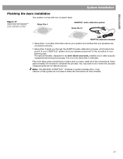
... speakers are connected correctly. • Setup Disc 2 leads you through the ADAPTiQ audio calibration process, which tailors the sound of your LIFESTYLE® system and your speaker placement to be worn above your listening area. Put it when the acoustic measurements will not disturb anyone.... The special headset, designed to the acoustics of your ears, enables you have made all of the connections. Note: The 220-240V LIFESTYLE ® 18 Series II system includes Disc 1 only. English System Installation Finishing the basic installation Your system comes with two compact discs....
... speakers are connected correctly. • Setup Disc 2 leads you through the ADAPTiQ audio calibration process, which tailors the sound of your LIFESTYLE® system and your speaker placement to be worn above your listening area. Put it when the acoustic measurements will not disturb anyone.... The special headset, designed to the acoustics of your ears, enables you have made all of the connections. Note: The 220-240V LIFESTYLE ® 18 Series II system includes Disc 1 only. English System Installation Finishing the basic installation Your system comes with two compact discs....
