Owner's guide
Page 10
...amplified outputs for all channels. 1. The system input cable has a multi-pin connector on one end and several wire pairs on your surround receiver. CAUTION: Do not connect the powered Acoustimass module directly to the LFE/SUBWOOFER OUT jack. to -). • Attach each marked wire ...(+) to the appropriate + terminal. • Attach each plain wire (-) to the LFE/SUBWOOFER OUT jack on the other end of the connections (+...
...amplified outputs for all channels. 1. The system input cable has a multi-pin connector on one end and several wire pairs on your surround receiver. CAUTION: Do not connect the powered Acoustimass module directly to the LFE/SUBWOOFER OUT jack. to -). • Attach each marked wire ...(+) to the appropriate + terminal. • Attach each plain wire (-) to the LFE/SUBWOOFER OUT jack on the other end of the connections (+...
Owner's guide
Page 11
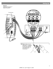
Figure 6 Acoustimass® module to receiver connections Thumbscrews Audio Output Left Rear Right Rear Audio Input Left Center Right Front Front Front Setting Up FRONT SPEAKERS A R L CENTER FRONT SPEAKERS A R L CENTER SURROUND SPEAKERS R L LFE/SUBWOOFER OUT Note: Cables may be separated or "unzipped" as much as needed to comfortably reach the surround receiver connections. 11 264887_00 _V.pdf • August 13, 2002
Figure 6 Acoustimass® module to receiver connections Thumbscrews Audio Output Left Rear Right Rear Audio Input Left Center Right Front Front Front Setting Up FRONT SPEAKERS A R L CENTER FRONT SPEAKERS A R L CENTER SURROUND SPEAKERS R L LFE/SUBWOOFER OUT Note: Cables may be separated or "unzipped" as much as needed to comfortably reach the surround receiver connections. 11 264887_00 _V.pdf • August 13, 2002


