Owner's guide
Page 3
... speakers to achieve realistic home theater sound 5 Front left and right speakers 6 Center speaker 6 Rear speakers 6 Powered Acoustimass® module 7 Making the connections 7 Connecting speakers to the Acoustimass module 7 Connecting the Acoustimass module to the receiver 9 Checking the connections 10 USING YOUR SYSTEM 11 Getting the most from your home theater speakers 11 Adjusting the bass/room compensation...
... speakers to achieve realistic home theater sound 5 Front left and right speakers 6 Center speaker 6 Rear speakers 6 Powered Acoustimass® module 7 Making the connections 7 Connecting speakers to the Acoustimass module 7 Connecting the Acoustimass module to the receiver 9 Checking the connections 10 USING YOUR SYSTEM 11 Getting the most from your home theater speakers 11 Adjusting the bass/room compensation...
Owner's guide
Page 7
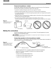
.... 7 Preferred Alternate Front opening Ventilation grille Making the connections Only the Acoustimass module connects to the Acoustimass module. Use the supplied 20-ft (6.1 m) speaker cables for your Acoustimass module SETTING UP Powered Acoustimass® module Acoustimass® speaker technology makes it difficult to locate the ...• Keep both the front opening toward a wall; Figure 4 Speaker cable connection to an output jack on the module and to the speaker Connecting speakers to the Acoustimass module Insert the connector on each connector to match it to the proper jack....
.... 7 Preferred Alternate Front opening Ventilation grille Making the connections Only the Acoustimass module connects to the Acoustimass module. Use the supplied 20-ft (6.1 m) speaker cables for your Acoustimass module SETTING UP Powered Acoustimass® module Acoustimass® speaker technology makes it difficult to locate the ...• Keep both the front opening toward a wall; Figure 4 Speaker cable connection to an output jack on the module and to the speaker Connecting speakers to the Acoustimass module Insert the connector on each connector to match it to the proper jack....
Owner's guide
Page 8
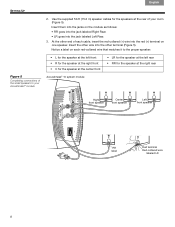
... each red-collared wire that matches it to the proper speaker: Figure 5 Completing connections of the small speakers to your room (Figure 5). Use the supplied 50-ft (15.2 m) speaker cables for the speaker at the rear of your Acoustimass® module • L for the speaker at the left front • R... for the speaker at the right front • C for the speaker at the center front Acoustimass® 10 system module • LR for the speaker at the left rear • RR for the speakers at the right rear Right front speaker Center front...
... each red-collared wire that matches it to the proper speaker: Figure 5 Completing connections of the small speakers to your room (Figure 5). Use the supplied 50-ft (15.2 m) speaker cables for the speaker at the rear of your Acoustimass® module • L for the speaker at the left front • R... for the speaker at the right front • C for the speaker at the center front Acoustimass® 10 system module • LR for the speaker at the left rear • RR for the speakers at the right rear Right front speaker Center front...
Owner's guide
Page 9
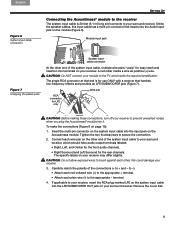
... on the system input cable into the input jack on page 10): 1. Acoustimass module. this input cable has a multi-pin connector that handles ! low-frequency effects and provides an LFE/SUBWOOFER jack (Figure 7). To make the connections (Figure 8 on the ! If applicable to the TV, ...and insertion into terminals on your surround receiver. English Español Français SETTING UP Figure 6 System input cable connection Connecting the Acoustimass® module to the receiver The system input cable is for use ONLY with a receiver that inserts into the Audio Input ...
... on the system input cable into the input jack on page 10): 1. Acoustimass module. this input cable has a multi-pin connector that handles ! low-frequency effects and provides an LFE/SUBWOOFER jack (Figure 7). To make the connections (Figure 8 on the ! If applicable to the TV, ...and insertion into terminals on your surround receiver. English Español Français SETTING UP Figure 6 System input cable connection Connecting the Acoustimass® module to the receiver The system input cable is for use ONLY with a receiver that inserts into the Audio Input ...
Owner's guide
Page 10
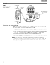
...) outlet. Note: Bose recommends using a quality surge suppressor on . Incorrect wiring can eliminate the vast majority of module output. • Correct any system. Using a highquality suppressor (available at electronics stores) can result in a total loss of failures caused by a power surge. 10 SETTING UP Figure 8 Acoustimass® module to receiver connections Thumbscrews Acoustimass® module...
...) outlet. Note: Bose recommends using a quality surge suppressor on . Incorrect wiring can eliminate the vast majority of module output. • Correct any system. Using a highquality suppressor (available at electronics stores) can result in a total loss of failures caused by a power surge. 10 SETTING UP Figure 8 Acoustimass® module to receiver connections Thumbscrews Acoustimass® module...
Owner's guide
Page 11
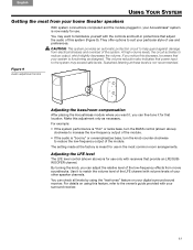
... input to reduce output, which slightly decreases the volume. Figure 9 Audio adjustment knobs Adjusting the bass/room compensation After placing the Acoustimass module where you can check all levels by using this decrease, be aware that your particular style of your other speaker channels. ... it for use only with the controls and built-in the most from your home theater speakers With system connections completed and the module plugged in, your Acoustimass® system is functioning as necessary. to help guard against damage from electrical stresses and overload of this...
... input to reduce output, which slightly decreases the volume. Figure 9 Audio adjustment knobs Adjusting the bass/room compensation After placing the Acoustimass module where you can check all levels by using this decrease, be aware that your particular style of your other speaker channels. ... it for use only with the controls and built-in the most from your home theater speakers With system connections completed and the module plugged in, your Acoustimass® system is functioning as necessary. to help guard against damage from electrical stresses and overload of this...
Owner's guide
Page 12
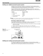
... setting LARGE LARGE LARGE ON Figure 10 Digital signal receiver connections Note: If your receiver. Be sure to adjust some! Français Español English USING YOUR SYSTEM Setting your digital surround sound receiver Speakers in the setup menu of your Acoustimass® 6 Series III or Acoustimass 10 Series IV system are fully ! compatible with your..., NOT both ) on the receiver and refer to reach your surround receiver. 12 To make changes, use the digital display menu on the receiver to connect to Wide.
... setting LARGE LARGE LARGE ON Figure 10 Digital signal receiver connections Note: If your receiver. Be sure to adjust some! Français Español English USING YOUR SYSTEM Setting your digital surround sound receiver Speakers in the setup menu of your Acoustimass® 6 Series III or Acoustimass 10 Series IV system are fully ! compatible with your..., NOT both ) on the receiver and refer to reach your surround receiver. 12 To make changes, use the digital display menu on the receiver to connect to Wide.
Owner's guide
Page 13
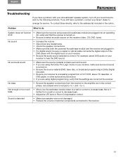
...to increase bass. Not enough or too much bass • Move your receiver to arrange for service. If you have a problem, contact your Bose® dealer to hear the DVD sound. Sound is distorted • Make sure speaker wire is correct. No sound • Increase the ...If you are using digital programming, verify that both the powered Acoustimass module and the receiver are plugged in. • For digital sound, be sure a coaxial or optical cable connects the digital output of external components connected to the amplifier are plugged into an operating at the receiver. ...
...to increase bass. Not enough or too much bass • Move your receiver to arrange for service. If you have a problem, contact your Bose® dealer to hear the DVD sound. Sound is distorted • Make sure speaker wire is correct. No sound • Increase the ...If you are using digital programming, verify that both the powered Acoustimass module and the receiver are plugged in. • For digital sound, be sure a coaxial or optical cable connects the digital output of external components connected to the amplifier are plugged into an operating at the receiver. ...
Owner's guide
Page 15
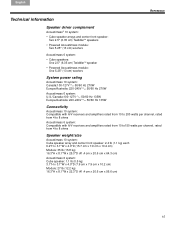
.../Australia: 220-240V 50/60 Hz 135W Connectivity Acoustimass 10 system: Compatible with A/V receivers and amplifiers rated from 10 to 200 watts per channel, rated from 4 to 8 ohms Acoustimass 6 system: Compatible with A/V receivers and amplifiers rated from 10 to150 watts per channel, rated from 4 to 8 ohms Speaker weight/size Acoustimass 10 system: Cube speaker array and center front...
.../Australia: 220-240V 50/60 Hz 135W Connectivity Acoustimass 10 system: Compatible with A/V receivers and amplifiers rated from 10 to 200 watts per channel, rated from 4 to 8 ohms Acoustimass 6 system: Compatible with A/V receivers and amplifiers rated from 10 to150 watts per channel, rated from 4 to 8 ohms Speaker weight/size Acoustimass 10 system: Cube speaker array and center front...


