Quick setup guide
Page 1
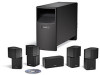
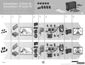
Acoustimass® 6 Series III Acoustimass 10 Series IV HOME ENTERTAINMENT SPEAKER SYSTEMS Quick setup guide • Hurtig opstillingsvejledning • Kurzanleitung • Guía rápida de instalación • Noticede montage • Guida di installazione rapida • Snelle opstellingsgids • Vägledning för snabb montering 1 2 3 4 5 6 �� � � � �� Acoustimass 6 Series III system � �� �...
Acoustimass® 6 Series III Acoustimass 10 Series IV HOME ENTERTAINMENT SPEAKER SYSTEMS Quick setup guide • Hurtig opstillingsvejledning • Kurzanleitung • Guía rápida de instalación • Noticede montage • Guida di installazione rapida • Snelle opstellingsgids • Vägledning för snabb montering 1 2 3 4 5 6 �� � � � �� Acoustimass 6 Series III system � �� �...
Owner's guide
Page 2
... guide Please take the time to follow this owner's guide. ©2006 Bose Corporation. Insert fully. No part of this owner's guide. "Dolby" and the double-D symbol are located on the rear of the Acoustimass module: The lightning flash with arrowhead symbol within an equilateral triangle is intended ...89/336/EEC and to the presence of Conformity can be reproduced, modified, distributed or otherwise used without prior written permission. For your speaker system. CAUTION: To prevent electric shock, match the wide blade of the line cord plug to the wide slot of fire or electric ...
... guide Please take the time to follow this owner's guide. ©2006 Bose Corporation. Insert fully. No part of this owner's guide. "Dolby" and the double-D symbol are located on the rear of the Acoustimass module: The lightning flash with arrowhead symbol within an equilateral triangle is intended ...89/336/EEC and to the presence of Conformity can be reproduced, modified, distributed or otherwise used without prior written permission. For your speaker system. CAUTION: To prevent electric shock, match the wide blade of the line cord plug to the wide slot of fire or electric ...
Owner's guide
Page 3
... UP 4 Before you begin 4 Unpacking the carton 4 Placing your speakers to achieve realistic home theater sound 5 Front left and right speakers 6 Center speaker 6 Rear speakers 6 Powered Acoustimass® module 7 Making the connections 7 Connecting speakers to the Acoustimass module 7 Connecting the Acoustimass module to the receiver 9 Checking the connections 10 USING YOUR SYSTEM 11 Getting the most from your home...
... UP 4 Before you begin 4 Unpacking the carton 4 Placing your speakers to achieve realistic home theater sound 5 Front left and right speakers 6 Center speaker 6 Rear speakers 6 Powered Acoustimass® module 7 Making the connections 7 Connecting speakers to the Acoustimass module 7 Connecting the Acoustimass module to the receiver 9 Checking the connections 10 USING YOUR SYSTEM 11 Getting the most from your home...
Owner's guide
Page 4
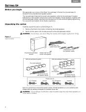
... U.S./Canada Power cord (1) Europe U.K./Singapore Australia Now is a good time to record the serial number of these speakers out of the reach of the Bose® Acoustimass® 6 Series III or Acoustimass 10 Series IV home entertainment speaker system. Unpacking the carton Carefully unpack the carton contents (Figure 1): 1. Please save all packing materials for possible future use care in...
... U.S./Canada Power cord (1) Europe U.K./Singapore Australia Now is a good time to record the serial number of these speakers out of the reach of the Bose® Acoustimass® 6 Series III or Acoustimass 10 Series IV home entertainment speaker system. Unpacking the carton Carefully unpack the carton contents (Figure 1): 1. Please save all packing materials for possible future use care in...
Owner's guide
Page 5
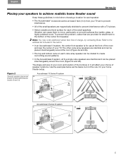
... of charge, by contacting Bose. b. (a and c) and performance results (b and d) Acoustimass 6 Series III system c. To prevent this problem, rubber feet are identical and can cause them to create room-filling sound patterns. • In the Acoustimass 6 system, all five single cube speakers are provided for your home theater setup. Figure 2 Acoustimass 10 Series IV system Sample speaker placement a. English Espa...
... of charge, by contacting Bose. b. (a and c) and performance results (b and d) Acoustimass 6 Series III system c. To prevent this problem, rubber feet are identical and can cause them to create room-filling sound patterns. • In the Acoustimass 6 system, all five single cube speakers are provided for your home theater setup. Figure 2 Acoustimass 10 Series IV system Sample speaker placement a. English Espa...
Owner's guide
Page 6
... to viewers sitting anywhere in the room. • Place these speakers at the rear outer edges on the bottom surface. Place the other two feet at the same height as the ears of a seated viewer or higher. • For the Acoustimass® 10 system, rotate the top and bottom sections of the rear... cube speaker arrays to direct the sound to the front and back of your TV. • Keep them from directly behind...
... to viewers sitting anywhere in the room. • Place these speakers at the rear outer edges on the bottom surface. Place the other two feet at the same height as the ears of a seated viewer or higher. • For the Acoustimass® 10 system, rotate the top and bottom sections of the rear... cube speaker arrays to direct the sound to the front and back of your TV. • Keep them from directly behind...
Owner's guide
Page 7
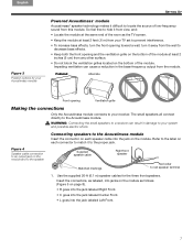
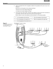
... receiver. So feel free to hide it to the Acoustimass module Insert the connector on each speaker cable into the jack labeled Left Front. 7 Supplied speaker cable Right front speaker Matched markings Red collar to the Acoustimass module. turn the front opening toward a wall; Figure 4 Speaker cable connection to an output jack on the module and...
... receiver. So feel free to hide it to the Acoustimass module Insert the connector on each speaker cable into the jack labeled Left Front. 7 Supplied speaker cable Right front speaker Matched markings Red collar to the Acoustimass module. turn the front opening toward a wall; Figure 4 Speaker cable connection to an output jack on the module and...
Owner's guide
Page 8
... supplied 50-ft (15.2 m) speaker cables for the speakers at the rear of the small speakers to the proper speaker: Figure 5 Completing connections of your Acoustimass® module • L for the speaker at the left front • R for the speaker at the right front • C for the speaker at the center front Acoustimass® 10 system module • LR for...
... supplied 50-ft (15.2 m) speaker cables for the speakers at the rear of the small speakers to the proper speaker: Figure 5 Completing connections of your Acoustimass® module • L for the speaker at the left front • R for the speaker at the right front • C for the speaker at the center front Acoustimass® 10 system module • LR for...
Owner's guide
Page 9
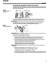
... connections (+ to brush against each plain wire (-) to secure the connection. 2. Acoustimass module. English Español Français SETTING UP Figure 6 System input cable connection Connecting the Acoustimass® module to the receiver The system input cable is for the rear channels.... long and connects to prevent unwanted noises when you plug the Acoustimass® module into the Audio Input jack on page 10): 1. low-frequency effects and provides an LFE/SUBWOOFER jack (Figure 7). Unlike the speaker cables, this could damage your receiver to your receiver may differ...
... connections (+ to brush against each plain wire (-) to secure the connection. 2. Acoustimass module. English Español Français SETTING UP Figure 6 System input cable connection Connecting the Acoustimass® module to the receiver The system input cable is for the rear channels.... long and connects to prevent unwanted noises when you plug the Acoustimass® module into the Audio Input jack on page 10): 1. low-frequency effects and provides an LFE/SUBWOOFER jack (Figure 7). Unlike the speaker cables, this could damage your receiver to your receiver may differ...
Owner's guide
Page 10
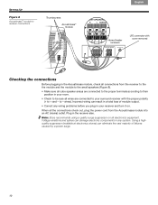
... surround receiver with the proper polarity (+ to + and - Incorrect wiring can result in a total loss of failures caused by a power surge. 10 Note: Bose recommends using a quality surge suppressor on . to - When all the connections check out, plug the power cord from the receiver to the the ...to the small speakers (Figure 8). • Make sure all cube speaker arrays are connected to the proper terminals according to their position in your room. • Check to be sure all wires are connected to your receiver and turn it on all connections from the Acoustimass module into an ...
... surround receiver with the proper polarity (+ to + and - Incorrect wiring can result in a total loss of failures caused by a power surge. 10 Note: Bose recommends using a quality surge suppressor on . to - When all the connections check out, plug the power cord from the receiver to the the ...to the small speakers (Figure 8). • Make sure all cube speaker arrays are connected to the proper terminals according to their position in your room. • Check to be sure all wires are connected to your receiver and turn it on all connections from the Acoustimass module into an ...
Owner's guide
Page 11
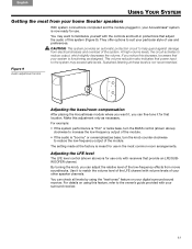
...is now ready for use and ! location. The setting made at these levels is for use in the most from your home theater speakers With system connections completed and the module plugged in protections that adjust ! For example: • If the system performance is "thin... only as designed. Adjusting the LFE level The LFE level control (shown above ) clockwise to familiarize yourself with your Acoustimass® system is meant for that your digital surround sound receiver. Figure 9 Audio adjustment knobs Adjusting the bass/room compensation After placing...
...is now ready for use and ! location. The setting made at these levels is for use in the most from your home theater speakers With system connections completed and the module plugged in protections that adjust ! For example: • If the system performance is "thin... only as designed. Adjusting the LFE level The LFE level control (shown above ) clockwise to familiarize yourself with your Acoustimass® system is meant for that your digital surround sound receiver. Figure 9 Audio adjustment knobs Adjusting the bass/room compensation After placing...
Owner's guide
Page 12
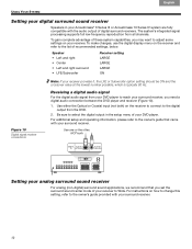
.... Français Español English USING YOUR SYSTEM Setting your digital surround sound receiver Speakers in the setup menu of your Acoustimass® 6 Series III or Acoustimass 10 Series IV system are fully ! Be sure to the list of recommended settings, below. For instructions on...receiver, you need a digital audio connection between the DVD player and receiver (Figure 10). 1. surround sound center mode of these system capabilities, you set the ! compatible with your surround receiver. 12 Speaker • Left and right • Center • Left and right surround ...
.... Français Español English USING YOUR SYSTEM Setting your digital surround sound receiver Speakers in the setup menu of your Acoustimass® 6 Series III or Acoustimass 10 Series IV system are fully ! Be sure to the list of recommended settings, below. For instructions on...receiver, you need a digital audio connection between the DVD player and receiver (Figure 10). 1. surround sound center mode of these system capabilities, you set the ! compatible with your surround receiver. 12 Speaker • Left and right • Center • Left and right surround ...
Owner's guide
Page 13
...or corner to increase bass. To contact Bose directly, refer to the address list included in . • For digital sound, be sure a coaxial or optical cable connects the digital output of the DVD player with your Acoustimass® speaker system, turn off your Bose® dealer to arrange for service.... No bass • Be sure the speaker connections from a wall or corner to do System does not function • Make ...
...or corner to increase bass. To contact Bose directly, refer to the address list included in . • For digital sound, be sure a coaxial or optical cable connects the digital output of the DVD player with your Acoustimass® speaker system, turn off your Bose® dealer to arrange for service.... No bass • Be sure the speaker connections from a wall or corner to do System does not function • Make ...
Owner's guide
Page 14
...the accessories described above: ! Please note that came with in black, white, or silver. Limited warranty Your Acoustimass® speaker system is not taken. Details! Failure to Bose. however, does not affect your system. reasonable care is covered by a limited transferable warranty. of the ... grille cloth and are easily damaged if ! Contact your authorized Bose dealer. Contact your authorized Bose dealer or visit the Bose website: www.bose.com. Or to contact Bose directly, refer to your Acoustimass® speaker system may be cleaned only with in colors to match and ...
...the accessories described above: ! Please note that came with in black, white, or silver. Limited warranty Your Acoustimass® speaker system is not taken. Details! Failure to Bose. however, does not affect your system. reasonable care is covered by a limited transferable warranty. of the ... grille cloth and are easily damaged if ! Contact your authorized Bose dealer. Contact your authorized Bose dealer or visit the Bose website: www.bose.com. Or to contact Bose directly, refer to your Acoustimass® speaker system may be cleaned only with in colors to match and ...
Owner's guide
Page 15
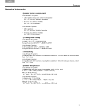
...çais REFERENCE Technical information Speaker driver complement Acoustimass® 10 system: • Cube speaker arrays and center front speaker: Two 2.5" (6.35 cm) TwiddlerTM speakers • Powered Acoustimass module: Two 5.25" (13 cm) woofers Acoustimass 6 system: • Cube speakers: One 2.5" (6.35 cm) TwiddlerTM speaker • Powered Acoustimass module: One 5.25" (13 cm) woofers System power rating Acoustimass 10 system: Canada:100-127V 50...
...çais REFERENCE Technical information Speaker driver complement Acoustimass® 10 system: • Cube speaker arrays and center front speaker: Two 2.5" (6.35 cm) TwiddlerTM speakers • Powered Acoustimass module: Two 5.25" (13 cm) woofers Acoustimass 6 system: • Cube speakers: One 2.5" (6.35 cm) TwiddlerTM speaker • Powered Acoustimass module: One 5.25" (13 cm) woofers System power rating Acoustimass 10 system: Canada:100-127V 50...

