

U8768 user's manual
Page 2
Table of U8768 7 2-2. Hardware...2 1-2. Layout of Contents Notice 1 Mainboard Features 2 1. Floppy Disk Connector: FDD1 16 4-5. Wake On LAN Header: JWOL1 16 4-6. Front USB Header: JUSB3 17 4-8. BIOS & Software 6 1-3. Mainboard Configuration 7 2-1. Component Index 8 3. Hard Disk Connectors: IDE1/IDE2 15 4-4. Front USB Header: JUSB4 17 4-9. 5V / 5VSB Selection for KB: JKBV1 17 i CPU Configuration 9 3-1. ATX 20...
Table of U8768 7 2-2. Hardware...2 1-2. Layout of Contents Notice 1 Mainboard Features 2 1. Floppy Disk Connector: FDD1 16 4-5. Wake On LAN Header: JWOL1 16 4-6. Front USB Header: JUSB3 17 4-8. BIOS & Software 6 1-3. Mainboard Configuration 7 2-1. Component Index 8 3. Hard Disk Connectors: IDE1/IDE2 15 4-4. Front USB Header: JUSB4 17 4-9. 5V / 5VSB Selection for KB: JKBV1 17 i CPU Configuration 9 3-1. ATX 20...
U8768 user's manual
Page 4
U8768 Features: 1.Contains on board I/O facilities that include two serial ports, a parallel port, a PS/2 mouse port, a PS/2 keyboard port, audio ports, USB ports and a game port. 2.... CD-ROM Drives. 3.Supports the Intel Pentium ® 4 processor, a leading edge processor. Chapter 1 Motherboard Description Notice Introduction of system This mainboard is designed to take advantage of its predecessors, this mainboard continues a commitment to provide you with the ultimate solution in data processing. In the tradition of the latest industry technology to...
U8768 Features: 1.Contains on board I/O facilities that include two serial ports, a parallel port, a PS/2 mouse port, a PS/2 keyboard port, audio ports, USB ports and a game port. 2.... CD-ROM Drives. 3.Supports the Intel Pentium ® 4 processor, a leading edge processor. Chapter 1 Motherboard Description Notice Introduction of system This mainboard is designed to take advantage of its predecessors, this mainboard continues a commitment to provide you with the ultimate solution in data processing. In the tradition of the latest industry technology to...
U8768 user's manual
Page 5
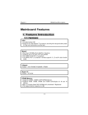
... and 16 devices. 3.Max of 2 Double-Sided DDR SDRAM with unbuffered / Registered. 4.The largest memory capacity is 2 GB. 1-2 VIA VT8753E (P4X266E)/ VT8235. Chapter 1 Motherboard Description Mainboard Features 1. ITE 8705 DRAM Memory: 1.Supports 200MHz, 266MHz DDR SDRAM devices. 2.Supports 64Mb, 128Mb, 256Mb and 512Mb technologies for high-end workstations and servers. Chipset...
... and 16 devices. 3.Max of 2 Double-Sided DDR SDRAM with unbuffered / Registered. 4.The largest memory capacity is 2 GB. 1-2 VIA VT8753E (P4X266E)/ VT8235. Chapter 1 Motherboard Description Mainboard Features 1. ITE 8705 DRAM Memory: 1.Supports 200MHz, 266MHz DDR SDRAM devices. 2.Supports 64Mb, 128Mb, 256Mb and 512Mb technologies for high-end workstations and servers. Chipset...
U8768 user's manual
Page 10
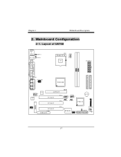
SECONDARY IDE CONN. Layout of U8768 JKBMS1 K/B & Mouse 1 JKBV1 JUSBLAN1 1 USB & LAN JUSBV1 JCOM1 CPU1 Socket 478 CPU J AT X P W R 1 COM1 Parallel Port COM2 PRIMARY IDE CONN. JPRNT1 JCOM2 J AT X P W R 2 P4X266E Game ... 1 1 JUSBV3 JUSBV4 VT8235 BAT1 24 23 BIOS 1 JCDIN1 PCI SLOT CNR1 CNR SLOT PCI3 21 JPANEL1 ITE I/O JWOL1 1 JCMOS1 1 FLOPPY DISK CONN. 1-7 Chapter 1 Motherboard Description 2. Mainboard Configuration 2-1.
SECONDARY IDE CONN. Layout of U8768 JKBMS1 K/B & Mouse 1 JKBV1 JUSBLAN1 1 USB & LAN JUSBV1 JCOM1 CPU1 Socket 478 CPU J AT X P W R 1 COM1 Parallel Port COM2 PRIMARY IDE CONN. JPRNT1 JCOM2 J AT X P W R 2 P4X266E Game ... 1 1 JUSBV3 JUSBV4 VT8235 BAT1 24 23 BIOS 1 JCDIN1 PCI SLOT CNR1 CNR SLOT PCI3 21 JPANEL1 ITE I/O JWOL1 1 JCMOS1 1 FLOPPY DISK CONN. 1-7 Chapter 1 Motherboard Description 2. Mainboard Configuration 2-1.
U8768 user's manual
Page 18
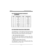
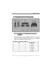
... 13 14 15 16 17 18 19 20 Assignment 3.3V -12V Ground PS_ON Ground Ground Ground -5V 5V 5V 4-3. Hard Disk Connectors: IDE1/IDE2 This mainboard has a 32-bit Enhanced PCI IDE Controller that provides PIO Mode 0~4, Bus Master, and Ultra DMA / 33, Ultra DMA / 66,Ultra DMA / 100, and Ultra...
... 13 14 15 16 17 18 19 20 Assignment 3.3V -12V Ground PS_ON Ground Ground Ground -5V 5V 5V 4-3. Hard Disk Connectors: IDE1/IDE2 This mainboard has a 32-bit Enhanced PCI IDE Controller that provides PIO Mode 0~4, Bus Master, and Ultra DMA / 33, Ultra DMA / 66,Ultra DMA / 100, and Ultra...

U8768 user's manual
Page 23
How to install DDR DIMM Module Single Sided DIMM Double Sided DIMM 1. The Mounting Holes and plastic tabs should fit over the edge and hold the DDR DIMM memory modules in one direction. 2. Insert the DDR DIMM memory modules into the socket at a 90-degree angle, then push down vertically so that it will fit into the slot in place. 20 Push the tabs out. The DDR DIMM socket has a " Plastic Safety Tab", and the DDR DIMM memory module has an Asymmetrical notch", so the DDR DIMM memory module can only fit into the place. 3. Mainboard Features 5-2.
How to install DDR DIMM Module Single Sided DIMM Double Sided DIMM 1. The Mounting Holes and plastic tabs should fit over the edge and hold the DDR DIMM memory modules in one direction. 2. Insert the DDR DIMM memory modules into the socket at a 90-degree angle, then push down vertically so that it will fit into the slot in place. 20 Push the tabs out. The DDR DIMM socket has a " Plastic Safety Tab", and the DDR DIMM memory module has an Asymmetrical notch", so the DDR DIMM memory module can only fit into the place. 3. Mainboard Features 5-2.
U8768 user's manual
Page 24
... PS/2 JUSBLAN1 Mouse LAN JPRNT1 Parallel JAUD_GAME Game Port PS/2 Keyboard USB COM1 COM2 Speaker Line In Mic Out In JCOM1 JCOM2 JSPKR1 JLIN1 JMIC1 6-1. Mainboard Features 6. You can plug a PS/2 mouse / Keyboard directly into this connector.
... PS/2 JUSBLAN1 Mouse LAN JPRNT1 Parallel JAUD_GAME Game Port PS/2 Keyboard USB COM1 COM2 Speaker Line In Mic Out In JCOM1 JCOM2 JSPKR1 JLIN1 JMIC1 6-1. Mainboard Features 6. You can plug a PS/2 mouse / Keyboard directly into this connector.

U8768 user's manual
Page 25
USB Connectors: USB Connector (the below one) Pin 1 2 3 4 USB Connector (the above one) Pin 5 6 7 8 Assignment +5 V (fused) USBP1USBP1+ Ground Assignment +5 V (fused) USBP2USBP2+ Ground 22 Mainboard Features 6-2. USB & LAN Port Connectors: JUSBLAN1 6-2-1.
USB Connectors: USB Connector (the below one) Pin 1 2 3 4 USB Connector (the above one) Pin 5 6 7 8 Assignment +5 V (fused) USBP1USBP1+ Ground Assignment +5 V (fused) USBP2USBP2+ Ground 22 Mainboard Features 6-2. USB & LAN Port Connectors: JUSBLAN1 6-2-1.

U8768 user's manual
Page 26
LAN Port Connector Pin 9 10 11 12 13 14 Assignment VCC3 TD+ TDRD+ RDNC 23 Mainboard Features 6-2-2. LAN Port Connector This connector allows you to connect to the Internet through a Local Area Network (LAN). You can set up the connection by entering account information provided by your ISP.
LAN Port Connector Pin 9 10 11 12 13 14 Assignment VCC3 TD+ TDRD+ RDNC 23 Mainboard Features 6-2-2. LAN Port Connector This connector allows you to connect to the Internet through a Local Area Network (LAN). You can set up the connection by entering account information provided by your ISP.

U8768 user's manual
Page 27
Mainboard Features 6-3. The Serial Interface: JCOM1/JCOM2 The serial interface port is sometimes referred to Send Ring Indicator DB9 PIN 1 2 3 4 5 6 7 8 9 DB25 PIN 8 3 2 20 7 6 4 5 22 24 Connectivity ...
Mainboard Features 6-3. The Serial Interface: JCOM1/JCOM2 The serial interface port is sometimes referred to Send Ring Indicator DB9 PIN 1 2 3 4 5 6 7 8 9 DB25 PIN 8 3 2 20 7 6 4 5 22 24 Connectivity ...

U8768 user's manual
Page 28
... -Auto FDXT 15 -Error 16 -Init 17 -SLCTN 18 Ground 19 Ground 20 Ground 21 Ground 22 Ground 23 Ground 24 Ground 25 Ground 25 Mainboard Features 6-3-2.
... -Auto FDXT 15 -Error 16 -Init 17 -SLCTN 18 Ground 19 Ground 20 Ground 21 Ground 22 Ground 23 Ground 24 Ground 25 Ground 25 Mainboard Features 6-3-2.

U8768 user's manual
Page 29
Game/Joystick/MIDI 6-5. Audio Port Connectors: JSPKR1/JLIN1/JMIC1 Speaker Out Line In Mic In 1. Mainboard Features 6-4. Also, you to the rear speakers while 26 Line In can be connected to connect speakers or headphones for audio input. 3. Speaker Out is ...
Game/Joystick/MIDI 6-5. Audio Port Connectors: JSPKR1/JLIN1/JMIC1 Speaker Out Line In Mic In 1. Mainboard Features 6-4. Also, you to the rear speakers while 26 Line In can be connected to connect speakers or headphones for audio input. 3. Speaker Out is ...

U8768 user's manual
Page 30
Mic In is enabled. 4 Channel S peakers 6 Channel S peakers Speaker Out Line In/ Mic In Rear Speaker Speaker Out Line In/ Mic In/ Center & Bass Rear Speaker 27 Center and Bass can be connected to center speaker and bass while six channel speakers mode is used to connect a microphone, which allows you to input sounds and voices. 5. Mainboard Features four/six channel speakers mode is enabled. 4.
Mic In is enabled. 4 Channel S peakers 6 Channel S peakers Speaker Out Line In/ Mic In Rear Speaker Speaker Out Line In/ Mic In/ Center & Bass Rear Speaker 27 Center and Bass can be connected to center speaker and bass while six channel speakers mode is used to connect a microphone, which allows you to input sounds and voices. 5. Mainboard Features four/six channel speakers mode is enabled. 4.
U8768 compatibility test report
Page 2
CONTENTS PRODUCT INFORMATION 4 Motherboard General Information 4 Chipset Details...4 BIOS Details...4 CPU Supports...4 Memory Supports 4 On-board Features and Devices 4 Mechanical...5 DESIGN REVIEW 7 Mainboard Voltage Measurement 7 Bus Clock ...7 REQUIRED BIOS DEFAULT SETTINGS 8 BIOS FEATURES SETUP 8 CHIPSET FEATURES SETUP 8 POWER MANAGEMENT SETUP 9 PnP / PCI CONFIGURATION 10 INTEGRATED PERIPHERALS 10 PC ...
CONTENTS PRODUCT INFORMATION 4 Motherboard General Information 4 Chipset Details...4 BIOS Details...4 CPU Supports...4 Memory Supports 4 On-board Features and Devices 4 Mechanical...5 DESIGN REVIEW 7 Mainboard Voltage Measurement 7 Bus Clock ...7 REQUIRED BIOS DEFAULT SETTINGS 8 BIOS FEATURES SETUP 8 CHIPSET FEATURES SETUP 8 POWER MANAGEMENT SETUP 9 PnP / PCI CONFIGURATION 10 INTEGRATED PERIPHERALS 10 PC ...

U8768 compatibility test report
Page 7
DESIGN REVIEW Mainboard Voltage Measurement Voltage List Battery Voltage Battery Current Voltage SPEC 3.0V 7uA Voltage Measured 3.09V 2.7uA +5V 5.0V+-5% 5.13 +12V -5V -12V 12.0V+-5% -5.0V+-5% -...
DESIGN REVIEW Mainboard Voltage Measurement Voltage List Battery Voltage Battery Current Voltage SPEC 3.0V 7uA Voltage Measured 3.09V 2.7uA +5V 5.0V+-5% 5.13 +12V -5V -12V 12.0V+-5% -5.0V+-5% -...