
User Manual
Page 2
TZ77XE4 UEFI BIOS Manual UEFI BIOS Setup Introduction The purpose of the booting process, loading and executing the operating system. The Setup program allows users to modify the basic system configuration and save these settings to describe the settings in UEFI BIOS Setup. BIOS activates at the first stage of this motherboard. This...
TZ77XE4 UEFI BIOS Manual UEFI BIOS Setup Introduction The purpose of the booting process, loading and executing the operating system. The Setup program allows users to modify the basic system configuration and save these settings to describe the settings in UEFI BIOS Setup. BIOS activates at the first stage of this motherboard. This...

User Manual
Page 3
...change the settings. We will see General Help description at the bottom right corner, and you will not be caused by wrong-settings. 2 TZ77XE4 UEFI BIOS Manual Supported CPUs This AMI UEFI BIOS supports the Intel CPU. Use Load Setup Default under the Exit Menu. The UEFI BIOS ...is for any settings, please load the default settings to be slightly different from this manual is being continuously updated. z The content of the motherboard. Using Setup When starting up the computer, press during the Power-On Self-Test (POST) to enter the UEFI BIOS setup utility. In the...
...change the settings. We will see General Help description at the bottom right corner, and you will not be caused by wrong-settings. 2 TZ77XE4 UEFI BIOS Manual Supported CPUs This AMI UEFI BIOS supports the Intel CPU. Use Load Setup Default under the Exit Menu. The UEFI BIOS ...is for any settings, please load the default settings to be slightly different from this manual is being continuously updated. z The content of the motherboard. Using Setup When starting up the computer, press during the Power-On Self-Test (POST) to enter the UEFI BIOS setup utility. In the...

Setup Manual
Page 2
Table of Contents Chapter 1: Introduction 1 1.1 Before You Start 1 1.2 Package Checklist 1 1.3 Motherboard Features 2 1.4 Rear Panel Connectors 4 1.5 Motherboard Layout 5 Chapter 2: Hardware Installation 6 2.1 Installing Central Processing Unit (CPU 6 2.2 FAN Headers 8 2.3 Installing System Memory 9 2.4 Connectors and Slots 11 Chapter 3: Headers & Jumpers Setup 15 3.1 How to ...
Table of Contents Chapter 1: Introduction 1 1.1 Before You Start 1 1.2 Package Checklist 1 1.3 Motherboard Features 2 1.4 Rear Panel Connectors 4 1.5 Motherboard Layout 5 Chapter 2: Hardware Installation 6 2.1 Installing Central Processing Unit (CPU 6 2.2 FAN Headers 8 2.3 Installing System Memory 9 2.4 Connectors and Slots 11 Chapter 3: Headers & Jumpers Setup 15 3.1 How to ...

Setup Manual
Page 3
... degrees Celsius. 1.2 PACKAGE CHECKLIST Serial ATA Cable X 4 Rear I/O Panel for choosing our product. CHAPTER 1: INTRODUCTION TZ77XE4 1.1 BEFORE YOU START Thank you take the motherboard out from dangerous area, such as heat source, humid air and water. „ The operating temperatures of the board... unless necessary. Before you start installing the motherboard, please make sure you follow the instructions below: „ Prepare a dry and stable working environment with sufficient lighting. „ Always...
... degrees Celsius. 1.2 PACKAGE CHECKLIST Serial ATA Cable X 4 Rear I/O Panel for choosing our product. CHAPTER 1: INTRODUCTION TZ77XE4 1.1 BEFORE YOU START Thank you take the motherboard out from dangerous area, such as heat source, humid air and water. „ The operating temperatures of the board... unless necessary. Before you start installing the motherboard, please make sure you follow the instructions below: „ Prepare a dry and stable working environment with sufficient lighting. „ Always...
Setup Manual
Page 4
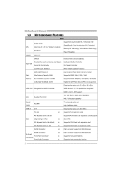
...(OC) / 2133(OC) / 2400(OC) 1GB/2GB/4GB/8GB DDR3 Registered DIMM and ECC DIMM is not supported Data transfer rates up to 3.0 Gb/s / 6.0 Gb/s. Motherboard Manual 1.3 MOTHERBOARD FEATURES SPEC Supports Execute Disable Bit / Enhanced Intel Socket 1155 SpeedStep® / Intel Architecture-64 / Extended CPU Intel Core i7 / i5 / i3 / Pentium / Celeron...
...(OC) / 2133(OC) / 2400(OC) 1GB/2GB/4GB/8GB DDR3 Registered DIMM and ECC DIMM is not supported Data transfer rates up to 3.0 Gb/s / 6.0 Gb/s. Motherboard Manual 1.3 MOTHERBOARD FEATURES SPEC Supports Execute Disable Bit / Enhanced Intel Socket 1155 SpeedStep® / Intel Architecture-64 / Extended CPU Intel Core i7 / i5 / i3 / Pentium / Celeron...

Setup Manual
Page 6
... ter Rear Side Line In Line Ou t Mic In NOTE: USB3.0 (only supported by Windows 7) ports are backward compatible with Display Port 1.1a NOTE: This motherboard supports dual video output: Display Devices VGA DVI-D HDMI Display Port VGA DVI-D HDMI X A A A A X S1, C, E A A S1, C, E X A Display Port A A A X z ... = Clone Mode z E = Extended Desktop Mode z S1 = Single Pipe Single Display With One Display Device Disabled z X = Unsupported / Note Applicable 4 Motherboard Manual 1.4 REAR PANEL CONNECTORS PS /2 Ke yb oard Display Port VGA eS ATA LA N USB2.0X2 HDMI DV I-
... ter Rear Side Line In Line Ou t Mic In NOTE: USB3.0 (only supported by Windows 7) ports are backward compatible with Display Port 1.1a NOTE: This motherboard supports dual video output: Display Devices VGA DVI-D HDMI Display Port VGA DVI-D HDMI X A A A A X S1, C, E A A S1, C, E X A Display Port A A A X z ... = Clone Mode z E = Extended Desktop Mode z S1 = Single Pipe Single Display With One Display Device Disabled z X = Unsupported / Note Applicable 4 Motherboard Manual 1.4 REAR PANEL CONNECTORS PS /2 Ke yb oard Display Port VGA eS ATA LA N USB2.0X2 HDMI DV I-
Setup Manual
Page 7
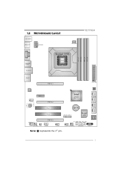
1.5 MOTHERBOARD LAYOUT USB_KBMS1 HDMI_DP1 ATXPW R1 TZ77XE4 CPU_FAN1 DDR3_A1 DDR3_A2 DDR3_B1 DDR3_B2 VGA1 DVI1 DUALUSB _ESATA1 RJ45USB1 Socket 1155 CP U 1 AUDIO1 PEX16_1 ATXPWR2 CO DEC_LE D_D2 CODE C_LE D_D1 LAN PEX1_1 F_AUDIO1 CODEC PEX16_2 PCI1 BIOS Intel Z77 BAT1 SATA2 SATA1 SATA4 SATA3 PCI2 JFRONT_USB3_1 Super I/O JSPDIFOUT1 PEX16_3 SYS_FAN1 CIR1 J_COM1 F_USB1 CL_CMOS_BTN RST_BTN F_USB2 SYS_FAN2 PWR_BTN PANEL1 Note: ■ represents the 1st pin. 5
1.5 MOTHERBOARD LAYOUT USB_KBMS1 HDMI_DP1 ATXPW R1 TZ77XE4 CPU_FAN1 DDR3_A1 DDR3_A2 DDR3_B1 DDR3_B2 VGA1 DVI1 DUALUSB _ESATA1 RJ45USB1 Socket 1155 CP U 1 AUDIO1 PEX16_1 ATXPWR2 CO DEC_LE D_D2 CODE C_LE D_D1 LAN PEX1_1 F_AUDIO1 CODEC PEX16_2 PCI1 BIOS Intel Z77 BAT1 SATA2 SATA1 SATA4 SATA3 PCI2 JFRONT_USB3_1 Super I/O JSPDIFOUT1 PEX16_3 SYS_FAN1 CIR1 J_COM1 F_USB1 CL_CMOS_BTN RST_BTN F_USB2 SYS_FAN2 PWR_BTN PANEL1 Note: ■ represents the 1st pin. 5

Setup Manual
Page 8
Remove Pin Cap before installation, and make good preservation for future use. Please refer below instruction to ensure pin legs won't be damaged. 2. Step 2: Remove the Pin Cap. 6 The motherboard might equip with two different types of pin cap. When the CPU is removed, cover the Pin Cap on the empty socket to remove the pin cap. Step 1: Pull the socket locking lever out from the socket and then raise the lever up. Motherboard Manual CHAPTER 2: HARDWARE INSTALLATION 2.1 INSTALLING CENTRAL PROCESSING UNIT (CPU) Notice: 1.
Remove Pin Cap before installation, and make good preservation for future use. Please refer below instruction to ensure pin legs won't be damaged. 2. Step 2: Remove the Pin Cap. 6 The motherboard might equip with two different types of pin cap. When the CPU is removed, cover the Pin Cap on the empty socket to remove the pin cap. Step 1: Pull the socket locking lever out from the socket and then raise the lever up. Motherboard Manual CHAPTER 2: HARDWARE INSTALLATION 2.1 INSTALLING CENTRAL PROCESSING UNIT (CPU) Notice: 1.

Setup Manual
Page 10
... connected to GND. 8 the CPU_FAN1 supports 4-pin head connector. Connect the fan cable to the connector while matching the black wire to the fan manufacturer. Motherboard Manual 2.2 FAN HEADERS These fan headers support cooling-fans built in the computer. When connecting with wires onto connectors, please note that the red wire...
... connected to GND. 8 the CPU_FAN1 supports 4-pin head connector. Connect the fan cable to the connector while matching the black wire to the fan manufacturer. Motherboard Manual 2.2 FAN HEADERS These fan headers support cooling-fans built in the computer. When connecting with wires onto connectors, please note that the red wire...

Setup Manual
Page 12
Motherboard Manual B. Memory Capacity DIMM Socket Location DDR3 Module DDR3_A1 512MB/1GB/2GB/4GB/8GB DDR3_A2 512MB/1GB/2GB/4GB/8GB DDR3_B1 512MB/1GB/2GB/4GB/...
Motherboard Manual B. Memory Capacity DIMM Socket Location DDR3 Module DDR3_A1 512MB/1GB/2GB/4GB/8GB DDR3_A2 512MB/1GB/2GB/4GB/8GB DDR3_B1 512MB/1GB/2GB/4GB/...
Setup Manual
Page 13
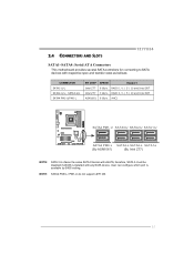
2.4 CONNECTORS AND SLOTS TZ77XE4 SATA1~SATA4: Serial ATA Connectors This motherboard provides several SATA controllers for connecting to SATA devices with eSATA; NOTE: SATA4 PM0-L / PM1-U do not support uEFI OS. 11 L SATA3-L SATA2-L SATA1-L (By ...
2.4 CONNECTORS AND SLOTS TZ77XE4 SATA1~SATA4: Serial ATA Connectors This motherboard provides several SATA controllers for connecting to SATA devices with eSATA; NOTE: SATA4 PM0-L / PM1-U do not support uEFI OS. 11 L SATA3-L SATA2-L SATA1-L (By ...

Setup Manual
Page 14
.... - PEX1_1: PCI-Express Gen2 x1 Slot - PCI-Express 3.0 compliant. - PCI-E 3.0 is x8. - The speed of PEX16_2 is supported by Core i7-3xxx / i5-3xxx CPU. Motherboard Manual PEX16_1/ PEX16_2: PCI-Express Gen3 x16 (x16 / x8) (Nvidia SLI and AMD CrossFireX) Slots -
.... - PEX1_1: PCI-Express Gen2 x1 Slot - PCI-Express 3.0 compliant. - PCI-E 3.0 is x8. - The speed of PEX16_2 is supported by Core i7-3xxx / i5-3xxx CPU. Motherboard Manual PEX16_1/ PEX16_2: PCI-Express Gen3 x16 (x16 / x8) (Nvidia SLI and AMD CrossFireX) Slots -

Setup Manual
Page 15
TZ77XE4 PCI1/PCI2: Peripheral Component Interconnect Slots This motherboard is 4-pin, please plug it is designated as 32 bits. If the CPU power plug is equipped with 2 standard PCI slots. This PCI slot is a bus standard for Peripheral Component Interconnect, and it into Pin 1-2-5-6 of ATXPWR2. 8 4 Pin Assignment 1 +12V 2 +12V 5 13 +12V 4 +12V 5 Ground 6 Ground 7 Ground 8 Ground 13 PCI 1 PCI2 ATXPWR1: ATX Power Source Connectors These connectors provide +12V to CPU power circuit. PCI stands for expansion cards.
TZ77XE4 PCI1/PCI2: Peripheral Component Interconnect Slots This motherboard is 4-pin, please plug it is designated as 32 bits. If the CPU power plug is equipped with 2 standard PCI slots. This PCI slot is a bus standard for Peripheral Component Interconnect, and it into Pin 1-2-5-6 of ATXPWR2. 8 4 Pin Assignment 1 +12V 2 +12V 5 13 +12V 4 +12V 5 Ground 6 Ground 7 Ground 8 Ground 13 PCI 1 PCI2 ATXPWR1: ATX Power Source Connectors These connectors provide +12V to CPU power circuit. PCI stands for expansion cards.

Setup Manual
Page 16
Motherboard Manual ATXPWR2: ATX Power Source Connector This connector allows user to connect 24-pin power connector on the ATX power supply. 12 24 1 13 Pin Assignment Pin Assignment 13 +3.3V 14 -12V 15 Ground 16 PS_ON 17 Ground 18 Ground 19 Ground 20 NC 21 +5V 22 +5V 23 +5V 24 Ground 1 +3.3V 2 +3.3V 3 Ground 4 +5V 5 Ground 6 +5V 7 Ground 8 PW_OK 9 Standby Voltage+5V 10 +12V 11 +12V 12 +3.3V Note: Before you power on the system, please make sure that ATXPWR1 and ATXPWR2 connectors have been well plugged-in. 14
Motherboard Manual ATXPWR2: ATX Power Source Connector This connector allows user to connect 24-pin power connector on the ATX power supply. 12 24 1 13 Pin Assignment Pin Assignment 13 +3.3V 14 -12V 15 Ground 16 PS_ON 17 Ground 18 Ground 19 Ground 20 NC 21 +5V 22 +5V 23 +5V 24 Ground 1 +3.3V 2 +3.3V 3 Ground 4 +5V 5 Ground 6 +5V 7 Ground 8 PW_OK 9 Standby Voltage+5V 10 +12V 11 +12V 12 +3.3V Note: Before you power on the system, please make sure that ATXPWR1 and ATXPWR2 connectors have been well plugged-in. 14

Setup Manual
Page 18
... D2- 13 Ground 14 SSTX2+ 15 SSTX2- 16 Ground 17 SSRX2+ 18 SSRX2- 19 VBUS1 20 Key NOTE: USB3.0 is only supported by Windows 7. 16 Motherboard Manual F_USB1/F_USB2: Headers for USB 3.0 Ports at Front Panel These headers allow user to connect additional USB cable on the PC front panel, and...
... D2- 13 Ground 14 SSTX2+ 15 SSTX2- 16 Ground 17 SSRX2+ 18 SSRX2- 19 VBUS1 20 Key NOTE: USB3.0 is only supported by Windows 7. 16 Motherboard Manual F_USB1/F_USB2: Headers for USB 3.0 Ports at Front Panel These headers allow user to connect additional USB cable on the PC front panel, and...

Setup Manual
Page 20
Motherboard Manual J_COM1: Serial Port Connector The motherboard has a Serial Port Connector for all the BIOS POST codes. 18 Please refer to Chapter 6.3 for connecting RS-232 Port. 2 10 1 9 Pin Assignment 1 Carrier detect 2 Received data 3 Transmitted data 4 Data terminal ready 5 Signal ground 6 Data set ready 7 Request to send 8 Clear to send 9 Ring indicator 10 NC BIOS POST Code/CPU Temperature Indicator This indicator will show POST code while booting. After the booting sequence, it will show current CPU temperature through hexadecimal figure.
Motherboard Manual J_COM1: Serial Port Connector The motherboard has a Serial Port Connector for all the BIOS POST codes. 18 Please refer to Chapter 6.3 for connecting RS-232 Port. 2 10 1 9 Pin Assignment 1 Carrier detect 2 Received data 3 Transmitted data 4 Data terminal ready 5 Signal ground 6 Data set ready 7 Request to send 8 Clear to send 9 Ring indicator 10 NC BIOS POST Code/CPU Temperature Indicator This indicator will show POST code while booting. After the booting sequence, it will show current CPU temperature through hexadecimal figure.

Setup Manual
Page 22
When the operating system installation starts, follow Windows indication by pressing F6 to enable RAID / AHCI Driver when installing Windows XP 1. Motherboard Manual CHAPTER 4: RAID / AHCI FUNCTIONS 4.1 OPERATING SYSTEM CHIP Intel Z77 SATA1-U/SATA1-L/ SATA2-U/SATA2-L/ SATA3-U/SATA3-L/ eSATA Intel Z77 SATA1-U/SATA1-L/ SATA2-U/SATA2-L/ SATA3-U/SATA3-L/ ...
When the operating system installation starts, follow Windows indication by pressing F6 to enable RAID / AHCI Driver when installing Windows XP 1. Motherboard Manual CHAPTER 4: RAID / AHCI FUNCTIONS 4.1 OPERATING SYSTEM CHIP Intel Z77 SATA1-U/SATA1-L/ SATA2-U/SATA2-L/ SATA3-U/SATA3-L/ eSATA Intel Z77 SATA1-U/SATA1-L/ SATA2-U/SATA2-L/ SATA3-U/SATA3-L/ ...

Setup Manual
Page 24
... and performs disk reads and writes across multiple drives in a RAID 0 array system. It breaks up to 6 or 8. Block 1 Block 3 Block 5 Block 2 Block 4 Block 6 22 Motherboard Manual 4.3 HOW RAID WORKS RAID 0: The controller "stripes" data across multiple drives in parallel. This technique reduces overall disk access time and offers high bandwidth...
... and performs disk reads and writes across multiple drives in a RAID 0 array system. It breaks up to 6 or 8. Block 1 Block 3 Block 5 Block 2 Block 4 Block 6 22 Motherboard Manual 4.3 HOW RAID WORKS RAID 0: The controller "stripes" data across multiple drives in parallel. This technique reduces overall disk access time and offers high bandwidth...

Setup Manual
Page 26
... RAID level 1. Fault Tolerance: Yes. May be stripped using RAID 0 techniques. Block 1 Block 3 Block 5 Block 1 Block 3 Block 5 Block 2 Block 4 Block 6 Block 2 Block 4 Block 6 24 Motherboard Manual RAID 10: RAID 1 drives can be simultaneously used with other RAID levels in a RAID 10 solution for improved resiliency, performance and rebuild performance. Features...
... RAID level 1. Fault Tolerance: Yes. May be stripped using RAID 0 techniques. Block 1 Block 3 Block 5 Block 1 Block 3 Block 5 Block 2 Block 4 Block 6 Block 2 Block 4 Block 6 24 Motherboard Manual RAID 10: RAID 1 drives can be simultaneously used with other RAID levels in a RAID 10 solution for improved resiliency, performance and rebuild performance. Features...

Setup Manual
Page 28
... better. Activate RAID mode from BIOS, and install operating system. 3. Double click it to the optical drive, and Install all processes finish, reboot the system. 4. Motherboard Manual 4.4 INTEL SMART RESPONSE TECHNOLOGY With Intel(R) Smart Response Technology, the performance of accelerated device has been enabled accelerated. 26 Install RAID drives (RAID 0, 1, 5) and...
... better. Activate RAID mode from BIOS, and install operating system. 3. Double click it to the optical drive, and Install all processes finish, reboot the system. 4. Motherboard Manual 4.4 INTEL SMART RESPONSE TECHNOLOGY With Intel(R) Smart Response Technology, the performance of accelerated device has been enabled accelerated. 26 Install RAID drives (RAID 0, 1, 5) and...


