
Setup Manual
Page 1
... not occur in a residential installation. Duplication of their respective companies. H55 HD Setup Manual FCC Information and Copyright This equipment has been tested and found in this user's manual. These limits are trademarks of this publication and to make changes to the contents here...beforehand. There is no representations or warranties with the limits of a Class B digital device, pursuant to Part 15 of this user's manual is not allowed without first obtaining the vendor's approval in writing. This equipment generates, uses, and can radiate radio frequency energy and,...
... not occur in a residential installation. Duplication of their respective companies. H55 HD Setup Manual FCC Information and Copyright This equipment has been tested and found in this user's manual. These limits are trademarks of this publication and to make changes to the contents here...beforehand. There is no representations or warranties with the limits of a Class B digital device, pursuant to Part 15 of this user's manual is not allowed without first obtaining the vendor's approval in writing. This equipment generates, uses, and can radiate radio frequency energy and,...

Setup Manual
Page 3
... a dry and stable working environment with sufficient lighting. „ Always disconnect the computer from power outlet before operation. „ Before you for ATX Case X 1 User's Manual X 1 Fully Setup Driver CD X 1 FDD Cable X 1 (optional) USB 2.0 Cable X1 (optional) Serial ATA Power Cable X 1 (optional) Note: The package contents may damage the equipment. „...
... a dry and stable working environment with sufficient lighting. „ Always disconnect the computer from power outlet before operation. „ Before you for ATX Case X 1 User's Manual X 1 Fully Setup Driver CD X 1 FDD Cable X 1 (optional) USB 2.0 Cable X1 (optional) Serial ATA Power Cable X 1 (optional) Note: The package contents may damage the equipment. „...
Setup Manual
Page 4
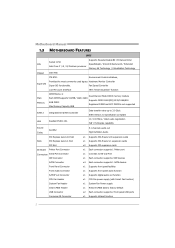
Motherboard Manual 1.3 MOTHERBOARD FEATURES SPEC Supports Execute Disable Bit / Enhanced Intel Socket 1156 CPU SpeedStep® / Intel Architecture-64 / Extended Intel Core i7 / i5 / i3/ Pentium processor ...
Motherboard Manual 1.3 MOTHERBOARD FEATURES SPEC Supports Execute Disable Bit / Enhanced Intel Socket 1156 CPU SpeedStep® / Intel Architecture-64 / Extended Intel Core i7 / i5 / i3/ Pentium processor ...

Setup Manual
Page 6
Motherboard Manual 1.5 MOTHERBOARD LAYOUT U S BK B 1 DD R 3_B 1 DD R 3_A 1 HDMI1 D V I1 Socket 1156 C PU 1 ID E 1 C P U_FA N1 ATX PW R 1 VGA1 SATA3 SATA1 SATA4 SATA2 JU S BV 1 R J 45U S B1 A U DI O1 ATX P WR 2 PEX16_1 BAT1 BIOS LAN PCI1 CODEC PCI2 J S P DI FOU T1 PEX1_1 Super I/O F_AUDIO1 J_PRINT1 J_COM1 H55 J U SB V 2 JCMOS1 SY S _FA N 1 CIR1 F_USB2 F_USB1 PANEL1 Note: ■ represents the 1st pin. 4
Motherboard Manual 1.5 MOTHERBOARD LAYOUT U S BK B 1 DD R 3_B 1 DD R 3_A 1 HDMI1 D V I1 Socket 1156 C PU 1 ID E 1 C P U_FA N1 ATX PW R 1 VGA1 SATA3 SATA1 SATA4 SATA2 JU S BV 1 R J 45U S B1 A U DI O1 ATX P WR 2 PEX16_1 BAT1 BIOS LAN PCI1 CODEC PCI2 J S P DI FOU T1 PEX1_1 Super I/O F_AUDIO1 J_PRINT1 J_COM1 H55 J U SB V 2 JCMOS1 SY S _FA N 1 CIR1 F_USB2 F_USB1 PANEL1 Note: ■ represents the 1st pin. 4
Setup Manual
Page 8
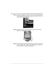
Step 5: Put the CPU Fan and heatsink assembly on the CPU and buckle it on CPU should point forwards this triangular cut edge. Step 4: Hold the CPU down firmly, and then lower the lever to locked position to complete the installation. 6 Connect the CPU FAN power cable into the CPU_FAN1 to complete the installation. The CPU will fit only in the correct orientation. Motherboard Manual Step 3: Look for the triangular cut edge on socket, and the golden dot on the retention frame.
Step 5: Put the CPU Fan and heatsink assembly on the CPU and buckle it on CPU should point forwards this triangular cut edge. Step 4: Hold the CPU down firmly, and then lower the lever to locked position to complete the installation. 6 Connect the CPU FAN power cable into the CPU_FAN1 to complete the installation. The CPU will fit only in the correct orientation. Motherboard Manual Step 3: Look for the triangular cut edge on socket, and the golden dot on the retention frame.

Setup Manual
Page 10
Insert the DIMM vertically and firmly into the slot until the retaining chip snap back in place and the DIMM is properly seated. 8 Motherboard Manual 2.3 INSTALLING SYSTEM MEMORY A. Unlock a DIMM slot by pressing the retaining clips outward. DDR3 module DDR 3_B1 DDR 3_A1 1. Align a DIMM on the slot such that the notch on the DIMM matches the break on the Slot. 2.
Insert the DIMM vertically and firmly into the slot until the retaining chip snap back in place and the DIMM is properly seated. 8 Motherboard Manual 2.3 INSTALLING SYSTEM MEMORY A. Unlock a DIMM slot by pressing the retaining clips outward. DDR3 module DDR 3_B1 DDR 3_A1 1. Align a DIMM on the slot such that the notch on the DIMM matches the break on the Slot. 2.
Setup Manual
Page 12
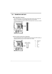
Motherboard Manual 2.4 CONNECTORS AND SLOTS IDE1: Hard Disk Connector The motherboard has a 32-bit Enhanced PCI IDE Controller that provides PIO Mode 0~4, Bus Master, and Ultra DMA ...
Motherboard Manual 2.4 CONNECTORS AND SLOTS IDE1: Hard Disk Connector The motherboard has a 32-bit Enhanced PCI IDE Controller that provides PIO Mode 0~4, Bus Master, and Ultra DMA ...
Setup Manual
Page 14
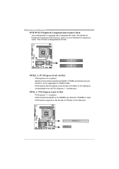
PEX16_1 PEX1_1 12 Motherboard Manual PCI1/PCI2: Peripheral Component Interconnect Slots This motherboard is designated as 32 bits. This PCI slot is equipped with 2 standard PCI slots. PCI-Express supports a ...
PEX16_1 PEX1_1 12 Motherboard Manual PCI1/PCI2: Peripheral Component Interconnect Slots This motherboard is designated as 32 bits. This PCI slot is equipped with 2 standard PCI slots. PCI-Express supports a ...

Setup Manual
Page 16
... panel, and also can be connected with internal USB devices, like USB card reader. JUSBV1 3 1 13 JUSBV2 13 Pin 1-2 close 13 Pin 2-3 close 14 Motherboard Manual F_USB1/F_USB2: Headers for USB 2.0 Ports at USBKB1/RJ45USB1. F_USB2 F_ USB1 2 10 1 9 Pin Assignment 1 +5V (fused) 2 +5V (fused) 3 USB4 USB5 USB+ 6 USB+ 7 Ground 8 Ground...
... panel, and also can be connected with internal USB devices, like USB card reader. JUSBV1 3 1 13 JUSBV2 13 Pin 1-2 close 13 Pin 2-3 close 14 Motherboard Manual F_USB1/F_USB2: Headers for USB 2.0 Ports at USBKB1/RJ45USB1. F_USB2 F_ USB1 2 10 1 9 Pin Assignment 1 +5V (fused) 2 +5V (fused) 3 USB4 USB5 USB+ 6 USB+ 7 Ground 8 Ground...

Setup Manual
Page 18
... detect 2 Received data 3 Transmitted data 4 Data terminal ready 5 Signal ground 6 Data set ready 7 Request to send 2 10 8 Clear to connector printer on the PC. Motherboard Manual J_PRINT1: Printer Port Connector This header allows you to send 9 Ring indicator 10 NC 1 9 16
... detect 2 Received data 3 Transmitted data 4 Data terminal ready 5 Signal ground 6 Data set ready 7 Request to send 2 10 8 Clear to connector printer on the PC. Motherboard Manual J_PRINT1: Printer Port Connector This header allows you to send 9 Ring indicator 10 NC 1 9 16
Setup Manual
Page 20
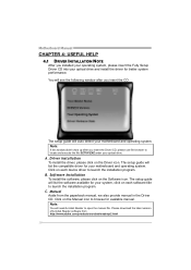
...install the software, please click on the Driver icon. C. Please download the latest version of Acrobat Reader software from the paperback manual, we also provide manual in the Driver CD. The setup guide will need Acrobat Reader to launch the installation program. Driver Installation To install the driver... for better system performance. The setup guide will auto detect your system, click on each device driver to open the manual file. Note: You will list the compatible driver for your optical drive and install the driver for your motherboard and operating system. ...
...install the software, please click on the Driver icon. C. Please download the latest version of Acrobat Reader software from the paperback manual, we also provide manual in the Driver CD. The setup guide will need Acrobat Reader to launch the installation program. Driver Installation To install the driver... for better system performance. The setup guide will auto detect your system, click on each device driver to open the manual file. Note: You will list the compatible driver for your optical drive and install the driver for your motherboard and operating system. ...
Setup Manual
Page 22
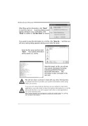
...txt file, you will see your system information including motherboard/BIOS/CPU/video/ device/OS information. Go to the following web http://www.biostar.com.tw/app/en-us/about/contact.php for your system information while using Outlook Express as your default e-mail client application, you ...txt file and send the file to our tech support with any other e-mail application. This information is also concluded in the sent mail. Motherboard Manual After filling up this information to a .txt file, click "Save As..." A warning dialog would appear asking for getting our contact information. 20...
...txt file, you will see your system information including motherboard/BIOS/CPU/video/ device/OS information. Go to the following web http://www.biostar.com.tw/app/en-us/about/contact.php for your system information while using Outlook Express as your default e-mail client application, you ...txt file and send the file to our tech support with any other e-mail application. This information is also concluded in the sent mail. Motherboard Manual After filling up this information to a .txt file, click "Save As..." A warning dialog would appear asking for getting our contact information. 20...
Setup Manual
Page 24
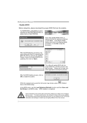
... doing this, please download the proper BIOS file from this manual. 22 All the information and content above are subject to be changed without notice. The information and pictures described above about the software are for ...
... doing this, please download the proper BIOS file from this manual. 22 All the information and content above are subject to be changed without notice. The information and pictures described above about the software are for ...
Setup Manual
Page 26
... process, the utility will ask you an easy and simple way to reboot the system. z This utility only allows storage device with BIO-Flasher 1. Motherboard Manual BIO-Flasher BIO-Flasher is built in the BIOS chip. Go to the website to system boot failure. 24 z Shutting down or resetting the system...
... process, the utility will ask you an easy and simple way to reboot the system. z This utility only allows storage device with BIO-Flasher 1. Motherboard Manual BIO-Flasher BIO-Flasher is built in the BIOS chip. Go to the website to system boot failure. 24 z Shutting down or resetting the system...
Setup Manual
Page 28
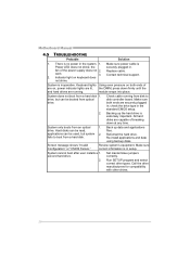
... applications and data using backup disks. System only boots from a hard disk. second hard drive. 2. There is no power in setup. Review system's equipment. Motherboard Manual 4.5 TROUBLESHOOTING Probable Solution 1. Contact technical support. 2.
... applications and data using backup disks. System only boots from a hard disk. second hard drive. 2. There is no power in setup. Review system's equipment. Motherboard Manual 4.5 TROUBLESHOOTING Probable Solution 1. Contact technical support. 2.

Bios Setup
Page 1
H55 HD BIOS Manual BIOS Setup 1 1 Main Menu 3 2 Advanced Menu 8 3 PCIPnP Menu 22 4 Boot Menu 25 5 Chipset Menu 28 6 Performance Menu 33 7 Exit Menu 36 i
H55 HD BIOS Manual BIOS Setup 1 1 Main Menu 3 2 Advanced Menu 8 3 PCIPnP Menu 22 4 Boot Menu 25 5 Chipset Menu 28 6 Performance Menu 33 7 Exit Menu 36 i
Bios Setup
Page 2
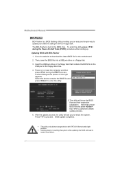
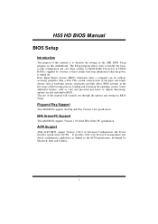
...by a battery so that it retains theSetup information when the power is to describe the settings in the AMI BIOS Setup program on this manual will to CMOS RAM. Some additional features, such as virus and password prot ection or chipset fine-tuning options are also included in ... PC Support T his AMI BIOS supports the Plug and Play Version 1.0A specification. T he rest of this motherboard. H55 HD BIOS Manual BIOS Setup Introduction T he purpose of this manual is turned off. Basic Input-Output System (BIOS) determines what a computer can do without accessing programs from a disk.
...by a battery so that it retains theSetup information when the power is to describe the settings in the AMI BIOS Setup program on this manual will to CMOS RAM. Some additional features, such as virus and password prot ection or chipset fine-tuning options are also included in ... PC Support T his AMI BIOS supports the Plug and Play Version 1.0A specification. T he rest of this motherboard. H55 HD BIOS Manual BIOS Setup Introduction T he purpose of this manual is turned off. Basic Input-Output System (BIOS) determines what a computer can do without accessing programs from a disk.
Bios Setup
Page 3
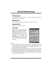
... unstable after changing any system damage that particular menu are at the bottom right corner, and you will not be slightly different from this manual is supported. Use Load Setup Default under the Exit Menu. DRAM S upport DDR3 SDRAM (Double Data Rate III Synchronous DRAM) is subject...to select item and ch ange the settings. z For better system perform ance, the BIOS firmware is providing a brief description of this manual. H55 HD BIOS Manual PCI Bus Support T his AMI BIOS supports the Intel CPU. We will see General Help description at the top right corner, and ...
... unstable after changing any system damage that particular menu are at the bottom right corner, and you will not be slightly different from this manual is supported. Use Load Setup Default under the Exit Menu. DRAM S upport DDR3 SDRAM (Double Data Rate III Synchronous DRAM) is subject...to select item and ch ange the settings. z For better system perform ance, the BIOS firmware is providing a brief description of this manual. H55 HD BIOS Manual PCI Bus Support T his AMI BIOS supports the Intel CPU. We will see General Help description at the top right corner, and ...

Bios Setup
Page 4
... Help F10 Save and Exit ESC Exit vxx.xx (C)Copyright 1985-200x, American Megatrends, Inc. System Time Set the system internal clock. H55 HD BIOS Manual 1 Main Menu Once you set the date. 3 Main Advanced BIOS SETUP UTILITY PCIPnP Boot Chipset Performance Exit System Overview AMI BIOS Version :01.01.01...
... Help F10 Save and Exit ESC Exit vxx.xx (C)Copyright 1985-200x, American Megatrends, Inc. System Time Set the system internal clock. H55 HD BIOS Manual 1 Main Menu Once you set the date. 3 Main Advanced BIOS SETUP UTILITY PCIPnP Boot Chipset Performance Exit System Overview AMI BIOS Version :01.01.01...

Bios Setup
Page 5
..., Inc. Options: Compatible (Default) / Enhanced 4 Options: IDE (Default) / AHCI / Disabled SATA#1 Configuration T his item allows you to choose the SAT A operation mode. H55 HD BIOS Manual IDE/S ATA Configuration T he BIOS will automatically detect the presence of detailed options.
..., Inc. Options: Compatible (Default) / Enhanced 4 Options: IDE (Default) / AHCI / Disabled SATA#1 Configuration T his item allows you to choose the SAT A operation mode. H55 HD BIOS Manual IDE/S ATA Configuration T he BIOS will automatically detect the presence of detailed options.

