
MANUAL
Page 1
...) SPDIF Cable x 1 (optional) i User's Manual The vendor makes no guarantee that interference will not be changed without first obtaining the vendor's approval in writing. Biostar T-Series TForce 945P FCC Information and Copyright This equipment has been tested and found in this user's manual. These limits are trademarks of this publication and to make...
...) SPDIF Cable x 1 (optional) i User's Manual The vendor makes no guarantee that interference will not be changed without first obtaining the vendor's approval in writing. Biostar T-Series TForce 945P FCC Information and Copyright This equipment has been tested and found in this user's manual. These limits are trademarks of this publication and to make...
MANUAL
Page 2
Biostar T-Series TForce 945P PACKAGE CHECKLIST I CHAPTER 1: INTRODUCTION 1 1.1 MOTHERBOARD FEATURES 1 1.2 LAYOUT AND COMPONENTS 3 CHAPTER 2: HARDWARE INSTALLATION 5 2.1 INSTALLING CENTRAL PRIOCESSING UNIT (CPU 5 2.2 SYSTEM MEMORY 7 2.3 PERIPHERALS 9 CHAPTER 3: OVERCLOCK QUICK GUIDE 20 3.1: T-...
Biostar T-Series TForce 945P PACKAGE CHECKLIST I CHAPTER 1: INTRODUCTION 1 1.1 MOTHERBOARD FEATURES 1 1.2 LAYOUT AND COMPONENTS 3 CHAPTER 2: HARDWARE INSTALLATION 5 2.1 INSTALLING CENTRAL PRIOCESSING UNIT (CPU 5 2.2 SYSTEM MEMORY 7 2.3 PERIPHERALS 9 CHAPTER 3: OVERCLOCK QUICK GUIDE 20 3.1: T-...
MANUAL
Page 3
... mode 0-4, Block Mode and Ultra DMA 33/66/100 bus master mode. 1 User's Manual Supports DDR2 400/533/667. Biostar T-Series TForce 945P CHAPTER 1: INTRODUCTION 1.1 MOTHERBOARD FEATURES CPU Supports LGA 775. Supports Intel Pentium 4 processor and Celeron D. Chipset North Bridge: Intel... 945P South Bridge: Intel ICH7. AC'97 Audio Sound Codec Chip: REALTEK ALC655, supports 6 channels audio output. Operating Systems Supports...
... mode 0-4, Block Mode and Ultra DMA 33/66/100 bus master mode. 1 User's Manual Supports DDR2 400/533/667. Biostar T-Series TForce 945P CHAPTER 1: INTRODUCTION 1.1 MOTHERBOARD FEATURES CPU Supports LGA 775. Supports Intel Pentium 4 processor and Celeron D. Chipset North Bridge: Intel... 945P South Bridge: Intel ICH7. AC'97 Audio Sound Codec Chip: REALTEK ALC655, supports 6 channels audio output. Operating Systems Supports...

MANUAL
Page 4
Biostar T-Series TForce 945P Gigabit Ethernet LAN PHY: RTL 8110S-32 / 8110SC. Internal On-board Slots and Connectors 1 floppy connector. 1 PCI-Express x16 slot. 2 PCI-Express x1 slots. 1 CD-...
Biostar T-Series TForce 945P Gigabit Ethernet LAN PHY: RTL 8110S-32 / 8110SC. Internal On-board Slots and Connectors 1 floppy connector. 1 PCI-Express x16 slot. 2 PCI-Express x1 slots. 1 CD-...
MANUAL
Page 5
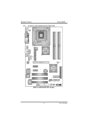
SATA4 IR JPANEL1 (optional ) 3 User's Manual Biostar T-Series TForce 945P 1.2 LAYOUT AND COMPONENTS (VER 1.X) JKBMS1 JKBV1 LGA775 COJMC1OM1 CPU1 JPRNT1 DDR2_A1 DDR2_A2 DDR2_B1 DDR2_B2 JUSB2 JRJ45USB1 JATXPWR2 JCFAN1 Intel 945P JAUDIO1 JAUDIO6 JCDIN1 Codec JATXPWR1 PCI-Ex16 JDDR2_OV_3V Super I/O PCI-Ex1_1 PCI-Ex1_2 BAT1 Intel ICH7 IDE1 BIOS PCI1 PCI2 SATA1 SATA3 JCI1 10/100 LAN PCI3 JSFAN1 JCMOS1 SATA2 JUSB3 JUSB4 FDD1 JSPDIF_OUT1 Note: ■ represents the 1st pin.
SATA4 IR JPANEL1 (optional ) 3 User's Manual Biostar T-Series TForce 945P 1.2 LAYOUT AND COMPONENTS (VER 1.X) JKBMS1 JKBV1 LGA775 COJMC1OM1 CPU1 JPRNT1 DDR2_A1 DDR2_A2 DDR2_B1 DDR2_B2 JUSB2 JRJ45USB1 JATXPWR2 JCFAN1 Intel 945P JAUDIO1 JAUDIO6 JCDIN1 Codec JATXPWR1 PCI-Ex16 JDDR2_OV_3V Super I/O PCI-Ex1_1 PCI-Ex1_2 BAT1 Intel ICH7 IDE1 BIOS PCI1 PCI2 SATA1 SATA3 JCI1 10/100 LAN PCI3 JSFAN1 JCMOS1 SATA2 JUSB3 JUSB4 FDD1 JSPDIF_OUT1 Note: ■ represents the 1st pin.

MANUAL
Page 6
Biostar T-Series TForce 945P 1.3 LAYOUT AND COMPONENTS (VER 2.X) JKBMS1 JKBV1 LGA775 COJMC1OM1 CPU1 JPRNT1 DDR2_A1 DDR2_A2 DDR2_B1 DDR2_B2 JUSB2 JRJ45USB1 JATXPWR2 JCFAN1 Intel 945P JAUDIO1 JAUDIO6 JCDIN1 Codec JATXPWR1 PCI-Ex16 JDDRII_2.2V Super I/O PCI-Ex1_1 PCI-Ex1_2 BAT1 Intel ICH7 IDE1 BIOS PCI1 PCI2 SATA1 SATA3 JCI1 10/100 LAN PCI3 JSFAN1 JCMOS1 SATA2 JUSB3 JUSB4 FDD1 JSPDIF_OUT1 Note: ■ represents the 1st pin. SATA4 RSTSW1 JPANEL1 PWRSW1 4 User's Manual
Biostar T-Series TForce 945P 1.3 LAYOUT AND COMPONENTS (VER 2.X) JKBMS1 JKBV1 LGA775 COJMC1OM1 CPU1 JPRNT1 DDR2_A1 DDR2_A2 DDR2_B1 DDR2_B2 JUSB2 JRJ45USB1 JATXPWR2 JCFAN1 Intel 945P JAUDIO1 JAUDIO6 JCDIN1 Codec JATXPWR1 PCI-Ex16 JDDRII_2.2V Super I/O PCI-Ex1_1 PCI-Ex1_2 BAT1 Intel ICH7 IDE1 BIOS PCI1 PCI2 SATA1 SATA3 JCI1 10/100 LAN PCI3 JSFAN1 JCMOS1 SATA2 JUSB3 JUSB4 FDD1 JSPDIF_OUT1 Note: ■ represents the 1st pin. SATA4 RSTSW1 JPANEL1 PWRSW1 4 User's Manual
MANUAL
Page 7
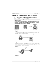
Biostar T-Series TForce 945P CHAPTER 2: HARDWARE INSTALLATION 2.1 INSTALLING CENTRAL PROCESSING UNIT (CPU) A. When the CPU is removed, cover the Pin Cap on CPU should point towards this triangular cut ...
Biostar T-Series TForce 945P CHAPTER 2: HARDWARE INSTALLATION 2.1 INSTALLING CENTRAL PROCESSING UNIT (CPU) A. When the CPU is removed, cover the Pin Cap on CPU should point towards this triangular cut ...
MANUAL
Page 8
... should be connected to complete the installation. This completes the installation. Connect the CPU FAN power cable into the JCFAN1. It supports 4 pin head connector. Biostar T-Series TForce 945P Step 3: Hold the CPU down firmly, and then lower the lever to locked position to GND. 6 User's Manual B. When connecting with Smart Fan Control...
... should be connected to complete the installation. This completes the installation. Connect the CPU FAN power cable into the JCFAN1. It supports 4 pin head connector. Biostar T-Series TForce 945P Step 3: Hold the CPU down firmly, and then lower the lever to locked position to GND. 6 User's Manual B. When connecting with Smart Fan Control...
MANUAL
Page 9
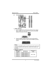
Unlock a DIMM slot by pressing the retaining clips outward. B. Biostar T-Series 2.2 SYSTEM MEMORY TForce 945P DDR2_A1 DDR2_A2 DDR2_B1 DDR2_B2 A. Notes: To remove the DDR modules, push the ejector tabs at both sides of the slot outward at the same time, ...
Unlock a DIMM slot by pressing the retaining clips outward. B. Biostar T-Series 2.2 SYSTEM MEMORY TForce 945P DDR2_A1 DDR2_A2 DDR2_B1 DDR2_B2 A. Notes: To remove the DDR modules, push the ejector tabs at both sides of the slot outward at the same time, ...
MANUAL
Page 10
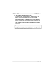
Biostar T-Series TForce 945P C. Dual Channel Memory installation To trigger the Duo Channel function of the motherboard, the memory module must meet the following requirements: Install Memory module of the same capacity in both channel 1 (DDR2_A1&DDR2_A2) and Channel 2 (DDR2_B1&DDR2_B2) The DRAM bus width of the memory module must be the same (x8 or x16) Notes: Using different memory chips on dual channel memory modules will result in unstable system performance. 8 User's Manual
Biostar T-Series TForce 945P C. Dual Channel Memory installation To trigger the Duo Channel function of the motherboard, the memory module must meet the following requirements: Install Memory module of the same capacity in both channel 1 (DDR2_A1&DDR2_A2) and Channel 2 (DDR2_B1&DDR2_B2) The DRAM bus width of the memory module must be the same (x8 or x16) Notes: Using different memory chips on dual channel memory modules will result in unstable system performance. 8 User's Manual
MANUAL
Page 11
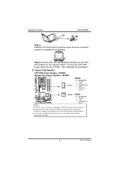
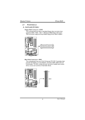
... 2 Hard Disk Connectors: IDE1 The motherboard has one 32-bit Enhanced PCI IDE Controllers that supports 360K, 720K, 1.2M, 1.44M and 2.88M floppy disk types. Biostar T-Series TForce 945P 2.3 PERIPHERALS A. The IDE connectors can connect a master and a slave drive, so you can connect 2 hard disk drives. 40 39 IDE1 2 1 9 User's Manual Card and...
... 2 Hard Disk Connectors: IDE1 The motherboard has one 32-bit Enhanced PCI IDE Controllers that supports 360K, 720K, 1.2M, 1.44M and 2.88M floppy disk types. Biostar T-Series TForce 945P 2.3 PERIPHERALS A. The IDE connectors can connect a master and a slave drive, so you can connect 2 hard disk drives. 40 39 IDE1 2 1 9 User's Manual Card and...
MANUAL
Page 12
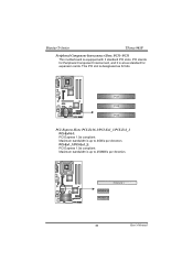
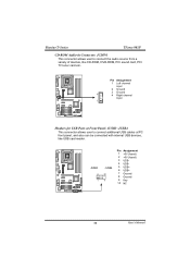
... it is up to 4GB/s per direction. This PCI slot is equipped with 3 standard PCI slots. PCI-Ex16-1 PCI-Ex1_1 PCI-Ex1_2 10 User's Manual Biostar T-Series TForce 945P Peripheral Component Interconnect Slots: PCI1~PCI3 This motherboard is designated as 32 bits. PCI stands for expansion cards.
... it is up to 4GB/s per direction. This PCI slot is equipped with 3 standard PCI slots. PCI-Ex16-1 PCI-Ex1_1 PCI-Ex1_2 10 User's Manual Biostar T-Series TForce 945P Peripheral Component Interconnect Slots: PCI1~PCI3 This motherboard is designated as 32 bits. PCI stands for expansion cards.

MANUAL
Page 13
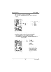
Biostar T-Series TForce 945P B. Pin opened Pin closed Pin1-2 closed ATX Power Source Connector: JATXPWR1 JATXPWR1 allows user to set up jumpers. When the jumper cap is placed on ...
Biostar T-Series TForce 945P B. Pin opened Pin closed Pin1-2 closed ATX Power Source Connector: JATXPWR1 JATXPWR1 allows user to set up jumpers. When the jumper cap is placed on ...
MANUAL
Page 14
Pin 2-3 Close: PS/2 keyboard and mouse are powered with +5V standby voltage. 3 1 3 1 Pin 1-2 close 3 1 Pin 2-3 close Note: In order to CPU power circuit. Pin Assignment 14 1 +12V 2 +12V 23 3 Ground 4 Ground Power Source Header for PS/2 Keyboard/Mouse: JKBV1 Pin 1-2 Close: +5V for PS/2 keyboard and mouse. Biostar T-Series TForce 945P ATX Power Source Connector: JATXPWR2 By connecting JATXPWR2, it will provide +12V to support this function "Power-on system via keyboard and mouse," JKBV1 jumper cap should be placed on Pin 2-3. 12 User's Manual
Pin 2-3 Close: PS/2 keyboard and mouse are powered with +5V standby voltage. 3 1 3 1 Pin 1-2 close 3 1 Pin 2-3 close Note: In order to CPU power circuit. Pin Assignment 14 1 +12V 2 +12V 23 3 Ground 4 Ground Power Source Header for PS/2 Keyboard/Mouse: JKBV1 Pin 1-2 Close: +5V for PS/2 keyboard and mouse. Biostar T-Series TForce 945P ATX Power Source Connector: JATXPWR2 By connecting JATXPWR2, it will provide +12V to support this function "Power-on system via keyboard and mouse," JKBV1 jumper cap should be placed on Pin 2-3. 12 User's Manual
MANUAL
Page 15
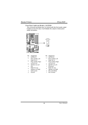
Biostar T-Series TForce 945P Front Panel Audio-out Header: JAUDIO6 This connector will disable the output on the PC case. It will allow user to connect with the front ...
Biostar T-Series TForce 945P Front Panel Audio-out Header: JAUDIO6 This connector will disable the output on the PC case. It will allow user to connect with the front ...
MANUAL
Page 16
Biostar T-Series TForce 945P CD-ROM Audio-in Connector: JCDIN1 This connector allows user to connect additional USB cables at Front Panel: JUSB3~JUSB4 This connector allows user to ...
Biostar T-Series TForce 945P CD-ROM Audio-in Connector: JCDIN1 This connector allows user to connect additional USB cables at Front Panel: JUSB3~JUSB4 This connector allows user to ...
MANUAL
Page 17
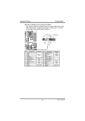
... button 19 Ground 20 Key 21 Ground 22 IRRX Function Sleep button N/A Power LED Power-on , Reset, HDD LED, Power LED, Sleep button, speaker Connection. Biostar T-Series TForce 945P JPANEL1: Header for Front Panel Facilities This 16-pin connector includes Power-on button IrDA Connector (Optional) 15 User's Manual
... button 19 Ground 20 Key 21 Ground 22 IRRX Function Sleep button N/A Power LED Power-on , Reset, HDD LED, Power LED, Sleep button, speaker Connection. Biostar T-Series TForce 945P JPANEL1: Header for Front Panel Facilities This 16-pin connector includes Power-on button IrDA Connector (Optional) 15 User's Manual
MANUAL
Page 18
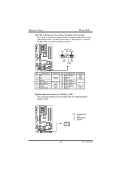
It allows user to connect the PCI bracket SPDIF output header. Pin Assignment 1 +5V 2 SPDIF OUT 3 Ground 31 16 User's Manual Biostar T-Series TForce 945P JPANEL1: Header for Front Panel Facilities (Ver 2.0 only) This 16-pin connector includes Power-on button Digital Audio-out Connector: JSPDIF_OUT1 This connector allows users ...
It allows user to connect the PCI bracket SPDIF output header. Pin Assignment 1 +5V 2 SPDIF OUT 3 Ground 31 16 User's Manual Biostar T-Series TForce 945P JPANEL1: Header for Front Panel Facilities (Ver 2.0 only) This 16-pin connector includes Power-on button Digital Audio-out Connector: JSPDIF_OUT1 This connector allows users ...

MANUAL
Page 19
JSATA1 JSATA3 741 JSATA2 JSATA4 Pin Assignment 1 Ground 2 TX+ 3 TX4 Ground 5 RX6 RX+ 7 Ground Case Open Header: JCI1 This connector allows system to the CMOS and show the message on next boot-up. Pin Assignment 1 Case open status. If the signal has been triggered, it will record to monitor PC case open signal 2 Ground 2 1 17 User's Manual Biostar T-Series TForce 945P Serial ATA Connectors: JSATA1~JSATA4 With the SATA Controller provided in the chipset, this motherboard supports 4 channel SATA II connectors. It satisfies the SATA 2.0 spec with transfer rate of 3.0 Gb/s.
JSATA1 JSATA3 741 JSATA2 JSATA4 Pin Assignment 1 Ground 2 TX+ 3 TX4 Ground 5 RX6 RX+ 7 Ground Case Open Header: JCI1 This connector allows system to the CMOS and show the message on next boot-up. Pin Assignment 1 Case open status. If the signal has been triggered, it will record to monitor PC case open signal 2 Ground 2 1 17 User's Manual Biostar T-Series TForce 945P Serial ATA Connectors: JSATA1~JSATA4 With the SATA Controller provided in the chipset, this motherboard supports 4 channel SATA II connectors. It satisfies the SATA 2.0 spec with transfer rate of 3.0 Gb/s.
MANUAL
Page 20
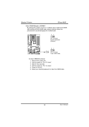
Power on pin 2-3, it allows user to restore the BIOS safe setting and the CMOS data, please carefully follow the procedures to avoid damaging the motherboard. 3 1 Pin 1-2 close: Normal Operation (Default). 3 1 3 1 Pin 2-3 close: Clear CMOS data. ※ Clear CMOS Procedures: 1. Remove AC power line. 2. Reset your desired password or clear the CMOS data. 18 User's Manual Biostar T-Series TForce 945P Clear CMOS Header: JCMOS1 By placing the jumper on the AC. 6. Wait for five seconds. 4. Set the jumper to "Pin 2-3 close ". 5. Set the jumper to "Pin 1-2 close ". 3.
Power on pin 2-3, it allows user to restore the BIOS safe setting and the CMOS data, please carefully follow the procedures to avoid damaging the motherboard. 3 1 Pin 1-2 close: Normal Operation (Default). 3 1 3 1 Pin 2-3 close: Clear CMOS data. ※ Clear CMOS Procedures: 1. Remove AC power line. 2. Reset your desired password or clear the CMOS data. 18 User's Manual Biostar T-Series TForce 945P Clear CMOS Header: JCMOS1 By placing the jumper on the AC. 6. Wait for five seconds. 4. Set the jumper to "Pin 2-3 close ". 5. Set the jumper to "Pin 1-2 close ". 3.


