

MOTHER BOARD MANUAL
Page 1
... for any implied warranties of the FCC Rules. The content of this user's manual is not allowed without notice and we will not occur in a residential installation. TF7150U-M7/TF7100P-M7 Setup Manual FCC Information and Copyright This equipment has been tested and found in this user...'s manual. All the brand and product names are designed to be changed without first obtaining the...
... for any implied warranties of the FCC Rules. The content of this user's manual is not allowed without notice and we will not occur in a residential installation. TF7150U-M7/TF7100P-M7 Setup Manual FCC Information and Copyright This equipment has been tested and found in this user...'s manual. All the brand and product names are designed to be changed without first obtaining the...

MOTHER BOARD MANUAL
Page 3
...static charge. „ Avoid touching the components on motherboard or the rear side of the board unless necessary. CHAPTER 1: INTRODUCTION TF7150U-M7/TF7100P-M7 1.1 BEFORE YOU START Thank you take the motherboard out from dangerous area, such as heat source, humid air and water. ...dry and stable working environment with sufficient lighting. „ Always disconnect the computer from power outlet before operation. „ Before you for ATX Case X 1 User's Manual X 1 Fully Setup Driver CD X 1 FDD Cable X 1 (optional) USB 2.0 Cable X1 (optional) S/PDIF out Cable X 1 (optional) Note: The ...
...static charge. „ Avoid touching the components on motherboard or the rear side of the board unless necessary. CHAPTER 1: INTRODUCTION TF7150U-M7/TF7100P-M7 1.1 BEFORE YOU START Thank you take the motherboard out from dangerous area, such as heat source, humid air and water. ...dry and stable working environment with sufficient lighting. „ Always disconnect the computer from power outlet before operation. „ Before you for ATX Case X 1 User's Manual X 1 Fully Setup Driver CD X 1 FDD Cable X 1 (optional) USB 2.0 Cable X1 (optional) S/PDIF out Cable X 1 (optional) Note: The ...

MOTHER BOARD MANUAL
Page 4
... Controller Integrated Serial ATA Controller SATA II Data transfer rates up to 3 Gb/s. SATA Version 2.0 specification compliant. Low Pin Count Interface Super I /O functionality. Motherboard Manual 1.3 MOTHERBOARD FEATURES TF7150U-M7 TF7100P-M7 LGA 775 LGA 775 Intel Core2Duo / Core2Quad / Celeron 4xx / Intel Core2Duo / Core2Quad / Celeron 4xx / Pentium D / Pentium 4 processor Pentium D / Pentium 4 processor Supports 45nm CPU...
... Controller Integrated Serial ATA Controller SATA II Data transfer rates up to 3 Gb/s. SATA Version 2.0 specification compliant. Low Pin Count Interface Super I /O functionality. Motherboard Manual 1.3 MOTHERBOARD FEATURES TF7150U-M7 TF7100P-M7 LGA 775 LGA 775 Intel Core2Duo / Core2Quad / Celeron 4xx / Intel Core2Duo / Core2Quad / Celeron 4xx / Pentium D / Pentium 4 processor Pentium D / Pentium 4 processor Supports 45nm CPU...

MOTHER BOARD MANUAL
Page 6
... transmitting digital video signals to digital display devices such as a digital television. \ D-Sub VGA Port Transmit analog video signals to different display panels simultaneously. 6 Motherboard Manual 1.4 REAR PANEL CONNECTORS X PS/2 Keyboard Port Y USB 2.0 Port x 2 Z DVI-D VGA Port The Digital Visual Interface (DVI) is an all-digital audio/video interface capable of...
... transmitting digital video signals to digital display devices such as a digital television. \ D-Sub VGA Port Transmit analog video signals to different display panels simultaneously. 6 Motherboard Manual 1.4 REAR PANEL CONNECTORS X PS/2 Keyboard Port Y USB 2.0 Port x 2 Z DVI-D VGA Port The Digital Visual Interface (DVI) is an all-digital audio/video interface capable of...

MOTHER BOARD MANUAL
Page 8
When the CPU is removed, cover the Pin Cap on the empty socket to a 90-degree angle. 8 Pin-Cap Step 1: Pull the socket locking lever out from the socket and then raise the lever up to ensure pin legs won't be damaged. Motherboard Manual CHAPTER 2: HARDWARE INSTALLATION 2.1 INSTALLING CENTRAL PROCESSING UNIT (CPU) Special Notice: Remove Pin Cap before installation, and make good preservation for future use.
When the CPU is removed, cover the Pin Cap on the empty socket to a 90-degree angle. 8 Pin-Cap Step 1: Pull the socket locking lever out from the socket and then raise the lever up to ensure pin legs won't be damaged. Motherboard Manual CHAPTER 2: HARDWARE INSTALLATION 2.1 INSTALLING CENTRAL PROCESSING UNIT (CPU) Special Notice: Remove Pin Cap before installation, and make good preservation for future use.

MOTHER BOARD MANUAL
Page 10
... to pin#2, and the black wire is Ground and should be different according to GND. 10 The JSFAN1 and JNFAN1 support 3-pin head connectors. Motherboard Manual 2.2 FAN HEADERS These fan headers support cooling-fans built in the computer. The fan cable and connector may be connected to the fan manufacturer. JCFAN1...
... to pin#2, and the black wire is Ground and should be different according to GND. 10 The JSFAN1 and JNFAN1 support 3-pin head connectors. Motherboard Manual 2.2 FAN HEADERS These fan headers support cooling-fans built in the computer. The fan cable and connector may be connected to the fan manufacturer. JCFAN1...

MOTHER BOARD MANUAL
Page 12
B. Memory Capacity DIMM Socket Location DIMMA1 DIMMA2 DDR2 Module 512MB/1024MB/2048MB 512MB/1024MB/2048MB Total Memory Size Max is properly seated. Motherboard Manual 2. Insert the DIMM vertically and firmly into the slot until the retaining chip snap back in place and the DIMM is 4GB. 12
B. Memory Capacity DIMM Socket Location DIMMA1 DIMMA2 DDR2 Module 512MB/1024MB/2048MB 512MB/1024MB/2048MB Total Memory Size Max is properly seated. Motherboard Manual 2. Insert the DIMM vertically and firmly into the slot until the retaining chip snap back in place and the DIMM is 4GB. 12

MOTHER BOARD MANUAL
Page 14
PCI stands for Peripheral Component Interconnect, and it is a bus standard for an aggregate of 8GB/s totally. Motherboard Manual PEX16_1: PCI-Express x16 Slot - PCI-Express 1.0a compliant. - Data transfer bandwidth up to 250MB/s per direction, for expansion cards. PCI-Express 1.0a compliant. - PCI-...
PCI stands for Peripheral Component Interconnect, and it is a bus standard for an aggregate of 8GB/s totally. Motherboard Manual PEX16_1: PCI-Express x16 Slot - PCI-Express 1.0a compliant. - Data transfer bandwidth up to 250MB/s per direction, for expansion cards. PCI-Express 1.0a compliant. - PCI-...

MOTHER BOARD MANUAL
Page 16
Motherboard Manual JATXPWR1: ATX Power Source Connector This connector allows user to connect 24-pin power connector on the ATX power supply. 12 24 Pin Assignment 13 +3....
Motherboard Manual JATXPWR1: ATX Power Source Connector This connector allows user to connect 24-pin power connector on the ATX power supply. 12 24 Pin Assignment 13 +3....

MOTHER BOARD MANUAL
Page 18
... the procedures to avoid damaging the motherboard. 13 Pin 1-2 Close: Normal Operation (default). 13 13 Pin 2-3 Close: Clear CMOS data. ※ Clear CMOS Procedures: 1. Motherboard Manual JCDIN1: CD-ROM Audio-in Connector This connector allows user to connect the audio source from the variaty devices, like CD-ROM, DVD-ROM, PCI...
... the procedures to avoid damaging the motherboard. 13 Pin 1-2 Close: Normal Operation (default). 13 13 Pin 2-3 Close: Clear CMOS data. ※ Clear CMOS Procedures: 1. Motherboard Manual JCDIN1: CD-ROM Audio-in Connector This connector allows user to connect the audio source from the variaty devices, like CD-ROM, DVD-ROM, PCI...

MOTHER BOARD MANUAL
Page 20
Pin Assignment 2 10 1 Carrier detect 2 Received data 3 Transmitted data 1 9 4 Data terminal ready 5 Signal ground 6 Data set ready 7 Request to send 8 Clear to connect the PCI bracket SPDIF output header. 13 Pin Assignment 1 +5V 2 SPDIF_OUT 3 Ground JCOM1: Serial port Connector The motherboard has a Serial Port Connector for connecting RS-232 Port. Motherboard Manual JSPDIF_OUT1: Digital Audio-out Connector This connector allows user to send 9 Ring indicator 10 Key 20
Pin Assignment 2 10 1 Carrier detect 2 Received data 3 Transmitted data 1 9 4 Data terminal ready 5 Signal ground 6 Data set ready 7 Request to send 8 Clear to connect the PCI bracket SPDIF output header. 13 Pin Assignment 1 +5V 2 SPDIF_OUT 3 Ground JCOM1: Serial port Connector The motherboard has a Serial Port Connector for connecting RS-232 Port. Motherboard Manual JSPDIF_OUT1: Digital Audio-out Connector This connector allows user to send 9 Ring indicator 10 Key 20

MOTHER BOARD MANUAL
Page 22
JUSBV2: USB ports at JUSB2/JUSB3/JUSB4 are powered by +5V standby voltage. 3 1 JUSBV1 3 1 Pin 1-2 close JUSBV2 13 3 1 Pin 2-3 close Note: In order to support this function "Power-On system via USB device," "JUSBV1/ JUSBV2" jumper cap should be placed on Pin 2-3 individually. 22 Pin 2-3 Close: JUSBV1: USB ports at JUSBKB1/JUSBLAN1 are powered by +5V standby voltage. Motherboard Manual JUSBV1/JUSBV2: Power Source Headers for USB Ports Pin 1-2 Close: JUSBV1: +5V for USB ports at JUSB2/JUSB3/JUSB4. JUSBV2: +5V for USB ports at JUSBKB1/JUSBLAN1.
JUSBV2: USB ports at JUSB2/JUSB3/JUSB4 are powered by +5V standby voltage. 3 1 JUSBV1 3 1 Pin 1-2 close JUSBV2 13 3 1 Pin 2-3 close Note: In order to support this function "Power-On system via USB device," "JUSBV1/ JUSBV2" jumper cap should be placed on Pin 2-3 individually. 22 Pin 2-3 Close: JUSBV1: USB ports at JUSBKB1/JUSBLAN1 are powered by +5V standby voltage. Motherboard Manual JUSBV1/JUSBV2: Power Source Headers for USB Ports Pin 1-2 Close: JUSBV1: +5V for USB ports at JUSB2/JUSB3/JUSB4. JUSBV2: +5V for USB ports at JUSBKB1/JUSBLAN1.

MOTHER BOARD MANUAL
Page 24
...be applied for small databases or any other drive. Drawbacks: Requires 2 drives for the storage space of a hardware failure. Motherboard Manual RAID 1: Every read and write is actually carried out in parallel across 2 disk drives in the array. The mirrored (backup) copy of... automatic backup that eliminates tedious manual backups to the other application that requires fault tolerance and minimal capacity. Benefits: Provides 100% data redundancy. RAID 1 provides a...
...be applied for small databases or any other drive. Drawbacks: Requires 2 drives for the storage space of a hardware failure. Motherboard Manual RAID 1: Every read and write is actually carried out in parallel across 2 disk drives in the array. The mirrored (backup) copy of... automatic backup that eliminates tedious manual backups to the other application that requires fault tolerance and minimal capacity. Benefits: Provides 100% data redundancy. RAID 1 provides a...

MOTHER BOARD MANUAL
Page 26
Motherboard Manual RAID 5: RAID 5 stripes both data and parity information across all the drives in the array. Features and Benefits Drives: Minimum 3. Uses: RAID 5 is ...
Motherboard Manual RAID 5: RAID 5 stripes both data and parity information across all the drives in the array. Features and Benefits Drives: Minimum 3. Uses: RAID 5 is ...
MOTHER BOARD MANUAL
Page 27
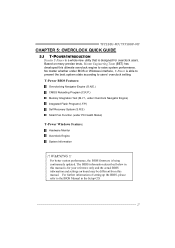
... described below in the Setup CD. 27 TF7150U-M7/TF7100P-M7 CHAPTER 5: OVERCLOCK QUICK GUIDE 5.1 T-POWER INTRODUCTION Biostar T-Power is a whole new utility that is designed for your reference only and the actual BIOS information and settings on many precise tests, Biostar Engineering Team (BET) has developed this manual. T-Power BIOS Features: Overclocking Navigator Engine (O.N.E.) CMOS...
... described below in the Setup CD. 27 TF7150U-M7/TF7100P-M7 CHAPTER 5: OVERCLOCK QUICK GUIDE 5.1 T-POWER INTRODUCTION Biostar T-Power is a whole new utility that is designed for your reference only and the actual BIOS information and settings on many precise tests, Biostar Engineering Team (BET) has developed this manual. T-Power BIOS Features: Overclocking Navigator Engine (O.N.E.) CMOS...

MOTHER BOARD MANUAL
Page 28
Overclocking Navigator Engine (O.N.E.): ONE provides two powerful overclocking engines: MOS and AOS for experienced overclock users. It allows users to customize personal overclock settings. ↓ 28 Manual Overclock System (M.O.S.) MOS is designed for both Elite and Casual overclockers. Motherboard Manual 5.2 T-POWER BIOS FEATURE A.
Overclocking Navigator Engine (O.N.E.): ONE provides two powerful overclocking engines: MOS and AOS for experienced overclock users. It allows users to customize personal overclock settings. ↓ 28 Manual Overclock System (M.O.S.) MOS is designed for both Elite and Casual overclockers. Motherboard Manual 5.2 T-POWER BIOS FEATURE A.

MOTHER BOARD MANUAL
Page 30
V12 Tech Engine: This setting will raise about 10%~15% of whole system performance. Notices: Not all types of whole system performance. Motherboard Manual V6 Tech Engine: This setting will raise about 25%~30% of whole system performance. V8 Tech Engine: This setting will be based on the selected CPU model. 30 the difference will raise about 15%~25% of AMD CPU perform above overclock setting ideally;
V12 Tech Engine: This setting will raise about 10%~15% of whole system performance. Notices: Not all types of whole system performance. Motherboard Manual V6 Tech Engine: This setting will raise about 25%~30% of whole system performance. V8 Tech Engine: This setting will be based on the selected CPU model. 30 the difference will raise about 15%~25% of AMD CPU perform above overclock setting ideally;

MOTHER BOARD MANUAL
Page 32
MIT allows users to ensure the memory stability. Motherboard Manual C. Run this test. ↓ Step 2: Save and Exit from "Enable" to "Disable" to activate this item is under "Overclocking Navigator Engine" item. Step 1: The default ...
MIT allows users to ensure the memory stability. Motherboard Manual C. Run this test. ↓ Step 2: Save and Exit from "Enable" to "Disable" to activate this item is under "Overclocking Navigator Engine" item. Step 1: The default ...

MOTHER BOARD MANUAL
Page 34
... is under "Smart Fan Option" in "PC Health Status". Smart Fan Function: Smart Fan Function is controlled automatically by CPU/System temperature. Fan speed. Motherboard Manual F. This is a brilliant feature to control CPU/System Temperature vs. This function will protect CPU/System from 0℃~127℃, with an interval of 1℃...
... is under "Smart Fan Option" in "PC Health Status". Smart Fan Function: Smart Fan Function is controlled automatically by CPU/System temperature. Fan speed. Motherboard Manual F. This is a brilliant feature to control CPU/System Temperature vs. This function will protect CPU/System from 0℃~127℃, with an interval of 1℃...

MOTHER BOARD MANUAL
Page 36
Motherboard Manual 5.3 T-POWER WINDOWS FEATURE 1. Now you double-click the desktop icon, T-Utility will be launched. Main Panel If you can launch the T-Utility simply by double-...
Motherboard Manual 5.3 T-POWER WINDOWS FEATURE 1. Now you double-click the desktop icon, T-Utility will be launched. Main Panel If you can launch the T-Utility simply by double-...

