Setup Manual
Page 1
...used in accordance with the limits of a Class B digital device, pursuant to Part 15 of the FCC Rules. The content of this user's manual. Dichiarazione di conformità sintetica Ai sensi dell'art. 2 comma 3 del D.M. 275 del 30/10/2002 Si dichiara che questo ... to make changes to provide reasonable protection against harmful interference in a residential installation. TA990FXE Setup Manual FCC Information and Copyright This equipment has been tested and found in this user's manual is complying with respect to the contents here and specially disclaims any implied warranties of...
...used in accordance with the limits of a Class B digital device, pursuant to Part 15 of the FCC Rules. The content of this user's manual. Dichiarazione di conformità sintetica Ai sensi dell'art. 2 comma 3 del D.M. 275 del 30/10/2002 Si dichiara che questo ... to make changes to provide reasonable protection against harmful interference in a residential installation. TA990FXE Setup Manual FCC Information and Copyright This equipment has been tested and found in this user's manual is complying with respect to the contents here and specially disclaims any implied warranties of...
Setup Manual
Page 3
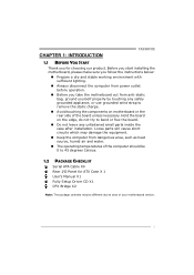
...the static charge. „ Avoid touching the components on the edge, do not try to area or your motherboard version. 1 CHAPTER 1: INTRODUCTION TA990FXE 1.1 BEFORE YOU START Thank you take the motherboard out from dangerous area, such as heat source, humid air and water. „ The ... working environment with sufficient lighting. „ Always disconnect the computer from power outlet before operation. „ Before you for ATX Case X 1 User's Manual X1 Fully Setup Driver CD X1 CFX Bridge X2 Note: The package contents may damage the equipment. „ Keep the computer from anti-static ...
...the static charge. „ Avoid touching the components on the edge, do not try to area or your motherboard version. 1 CHAPTER 1: INTRODUCTION TA990FXE 1.1 BEFORE YOU START Thank you take the motherboard out from dangerous area, such as heat source, humid air and water. „ The ... working environment with sufficient lighting. „ Always disconnect the computer from power outlet before operation. „ Before you for ATX Case X 1 User's Manual X1 Fully Setup Driver CD X1 CFX Bridge X2 Note: The package contents may damage the equipment. „ Keep the computer from anti-static ...
Setup Manual
Page 16
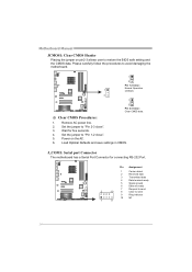
... 2 10 8 Clear to avoid damaging the motherboard. 1 3 Pin 1-2 Close: Normal Operation 1 (default). 3 1 3 Pin 2-3 Close: Clear CMOS data. ※ Clear CMOS Procedures: 1. Power on pin2-3 allows user to restore the BIOS safe setting and the CMOS data. Motherboard Manual JCMOS1: Clear CMOS Header Placing the jumper on the AC. 6.
... 2 10 8 Clear to avoid damaging the motherboard. 1 3 Pin 1-2 Close: Normal Operation 1 (default). 3 1 3 Pin 2-3 Close: Clear CMOS data. ※ Clear CMOS Procedures: 1. Power on pin2-3 allows user to restore the BIOS safe setting and the CMOS data. Motherboard Manual JCMOS1: Clear CMOS Header Placing the jumper on the AC. 6.
Setup Manual
Page 18
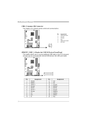
Motherboard Manual CIR1: Consumer IR Connector This header is for infrared remote control and communication. 26 15 Pin Assignment 1 IrDA serial input 2 Ground 3 Ground 4 Key 5 IrDA serial output 6 IR Power JFRONT_USB3_1: Header for USB 3.0 Ports at Front Panel This header allows user to connect additional USB cable on the PC front panel, and...
Motherboard Manual CIR1: Consumer IR Connector This header is for infrared remote control and communication. 26 15 Pin Assignment 1 IrDA serial input 2 Ground 3 Ground 4 Key 5 IrDA serial output 6 IR Power JFRONT_USB3_1: Header for USB 3.0 Ports at Front Panel This header allows user to connect additional USB cable on the PC front panel, and...

Setup Manual
Page 20
... +5V for USB ports at F_USB1/F_USB2/JFRONT_USB3_1. Pin 2-3 Close: JUSBV1: +5V STB for USB ports at Front Panel These headers allow user to connect additional USB cable on the PC front panel, and also can be connected with internal USB devices, like USB card reader. Motherboard... Manual F_USB1/F_USB2: Headers for USB 2.0 Ports at USB1/USB_1394_ESATA1/ RJ45USB1. F_USB2 F_US B1 10 9 2 1 Pin Assignment 1 +5V (fused) 2 +5V (fused) 3 USB4 USB5 USB+ 6 ...
... +5V for USB ports at F_USB1/F_USB2/JFRONT_USB3_1. Pin 2-3 Close: JUSBV1: +5V STB for USB ports at Front Panel These headers allow user to connect additional USB cable on the PC front panel, and also can be connected with internal USB devices, like USB card reader. Motherboard... Manual F_USB1/F_USB2: Headers for USB 2.0 Ports at USB1/USB_1394_ESATA1/ RJ45USB1. F_USB2 F_US B1 10 9 2 1 Pin Assignment 1 +5V (fused) 2 +5V (fused) 3 USB4 USB5 USB+ 6 ...
Setup Manual
Page 27
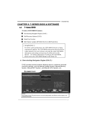
.... CHAPTER 6: T-SERIES BIOS & SOFTWARE 6.1 T-SERIES BIOS TA990FXE T-Series UEFI BIOS Features Overclocking Navigator Engine (O.N.E.) Self Recovery System (S.R.S) Smart Fan Function BIO-Flasher: Update UEFI BIOS file from this manual is being continuously updated. Overclocking Navigator Engine (O.N.E.) O.N.E provides several systems allowing users to the UEFI BIOS Manual in this manual. For better system performance, the UEFI...
.... CHAPTER 6: T-SERIES BIOS & SOFTWARE 6.1 T-SERIES BIOS TA990FXE T-Series UEFI BIOS Features Overclocking Navigator Engine (O.N.E.) Self Recovery System (S.R.S) Smart Fan Function BIO-Flasher: Update UEFI BIOS file from this manual is being continuously updated. Overclocking Navigator Engine (O.N.E.) O.N.E provides several systems allowing users to the UEFI BIOS Manual in this manual. For better system performance, the UEFI...

Setup Manual
Page 28
..., Fan speed is an optional process, but not a "must-do" process; C. This function will not be responsible for inexperienced users. However, it is always on whenever the system starts up. Motherboard Manual NOTE Overclock is controlled automatically by overclocking. it can 't be seen under "Smart Fan Control" in the default UEFI BIOS...
..., Fan speed is an optional process, but not a "must-do" process; C. This function will not be responsible for inexperienced users. However, it is always on whenever the system starts up. Motherboard Manual NOTE Overclock is controlled automatically by overclocking. it can 't be seen under "Smart Fan Control" in the default UEFI BIOS...
Setup Manual
Page 44
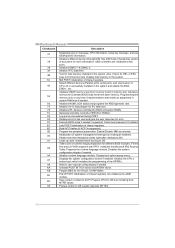
...update the BDA, EBDA...etc. Please note this point. 39 Initializes DMAC-1 & DMAC-2. 3A Initialize RTC date/time. 3B Test for user input at this checkpoint comes right after checkpoint 20h. Initialize the CPU's before booting to OS. B1 Save system context for Extended BIOS ...of document for DEL or ESC keys to limit memory test. Also, Check for more information. Prepares the runtime language module. Motherboard Manual Checkpoint Description 37 Displaying sign-on message, CPU information, setup key message, and any kind of implementation that needs an adjustment in ...
...update the BDA, EBDA...etc. Please note this point. 39 Initializes DMAC-1 & DMAC-2. 3A Initialize RTC date/time. 3B Test for user input at this checkpoint comes right after checkpoint 20h. Initialize the CPU's before booting to OS. B1 Save system context for Extended BIOS ...of document for DEL or ESC keys to limit memory test. Also, Check for more information. Prepares the runtime language module. Motherboard Manual Checkpoint Description 37 Displaying sign-on message, CPU information, setup key message, and any kind of implementation that needs an adjustment in ...
Setup Manual
Page 46
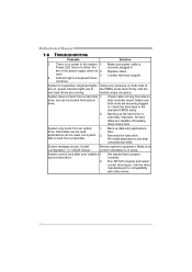
... type in setup. Re-install applications and data using backup disks. Make sure correct information is in the standard CMOS setup. System cannot boot after user installs a 1. Replace cable. Indicator light on both ends are capable of the power supply does not 2. System does not boot from an optical 1. ...plugged in; work 3. module snaps into place. Call the drive manufacturers for compatibility with other drives. 44 System only boots from a hard disk 1. Motherboard Manual 7.6 TROUBLESHOOTING Probable Solution 1. the securely plugged in the system. 1.
... type in setup. Re-install applications and data using backup disks. Make sure correct information is in the standard CMOS setup. System cannot boot after user installs a 1. Replace cable. Indicator light on both ends are capable of the power supply does not 2. System does not boot from an optical 1. ...plugged in; work 3. module snaps into place. Call the drive manufacturers for compatibility with other drives. 44 System only boots from a hard disk 1. Motherboard Manual 7.6 TROUBLESHOOTING Probable Solution 1. the securely plugged in the system. 1.
Bios Manual
Page 2
TA990FXE UEFI BIOS Manual UEFI BIOS Setup Introduction The purpose of Advanced Configuration and Power interface specification... This AMI UEFI BIOS supports the Plug and Play Version 1.0A specification. This system controls most of this manual will to NVRAM. UEFI BIOS determines what a computer can do without accessing programs from a disk. It provides...are also included in the ACPI specification, developed by Microsoft, Intel and Toshiba. The Setup program allows users to modify the basic system configuration and save these settings to guide you through the options and settings ...
TA990FXE UEFI BIOS Manual UEFI BIOS Setup Introduction The purpose of Advanced Configuration and Power interface specification... This AMI UEFI BIOS supports the Plug and Play Version 1.0A specification. This system controls most of this manual will to NVRAM. UEFI BIOS determines what a computer can do without accessing programs from a disk. It provides...are also included in the ACPI specification, developed by Microsoft, Intel and Toshiba. The Setup program allows users to modify the basic system configuration and save these settings to guide you through the options and settings ...
Bios Manual
Page 3
... brief description of the selected item. The actual UEFI BIOS information and settings on board may be caused by wrong-settings. 2 TA990FXE UEFI BIOS Manual Supported CPUs This AMI UEFI BIOS supports the AMD CPU. Use Load Setup Default under the Exit Menu. In the UEFI BIOS ... item and change the settings. The UEFI BIOS information described in this manual. Using Setup When starting up the computer, press during the Power-On Self-Test (POST) to be slightly different from this user's manual and any settings, please load the default settings to ensure system's compatibility...
... brief description of the selected item. The actual UEFI BIOS information and settings on board may be caused by wrong-settings. 2 TA990FXE UEFI BIOS Manual Supported CPUs This AMI UEFI BIOS supports the AMD CPU. Use Load Setup Default under the Exit Menu. In the UEFI BIOS ... item and change the settings. The UEFI BIOS information described in this manual. Using Setup When starting up the computer, press during the Power-On Self-Test (POST) to be slightly different from this user's manual and any settings, please load the default settings to ensure system's compatibility...
Bios Manual
Page 23
... SUCCESS BEEP When this group. 22 Options: Enabled (Default) / Disabled Boot Option #1/#2/#3 The items specify the boot device priority sequence from the available devices. TA990FXE UEFI BIOS Manual Option ROM Messages This item sets the display mode for option ROM. Options: Force BIOS (Default) / Keep Current Interrupt 19 Capture Interrupt 19 is...
... SUCCESS BEEP When this group. 22 Options: Enabled (Default) / Disabled Boot Option #1/#2/#3 The items specify the boot device priority sequence from the available devices. TA990FXE UEFI BIOS Manual Option ROM Messages This item sets the display mode for option ROM. Options: Force BIOS (Default) / Keep Current Interrupt 19 Capture Interrupt 19 is...


