Setup Manual
Page 1
TA990FXE Setup Manual FCC Information and Copyright This equipment has been tested and found in this user's manual. Dichiarazione di conformità sintetica Ai sensi dell'art. 2 comma 3 del D.M. 275 del 30/10/2002 Si dichiara che questo prodotto è conforme ... any purpose. Duplication of this publication and to make changes to radio communications. Further the vendor reserves the right to revise this user's manual is complying with the instructions, may cause harmful interference to the contents here without notice and we will not occur in accordance with the ...
TA990FXE Setup Manual FCC Information and Copyright This equipment has been tested and found in this user's manual. Dichiarazione di conformità sintetica Ai sensi dell'art. 2 comma 3 del D.M. 275 del 30/10/2002 Si dichiara che questo prodotto è conforme ... any purpose. Duplication of this publication and to make changes to radio communications. Further the vendor reserves the right to revise this user's manual is complying with the instructions, may cause harmful interference to the contents here without notice and we will not occur in accordance with the ...
Setup Manual
Page 3
... with sufficient lighting. „ Always disconnect the computer from power outlet before operation. „ Before you for ATX Case X 1 User's Manual X1 Fully Setup Driver CD X1 CFX Bridge X2 Note: The package contents may damage the equipment. „ Keep the computer from anti-static...which may be 0 to 45 degrees Celsius. 1.2 PACKAGE CHECKLIST Serial ATA Cable X4 Rear I/O Panel for choosing our product. CHAPTER 1: INTRODUCTION TA990FXE 1.1 BEFORE YOU START Thank you take the motherboard out from dangerous area, such as heat source, humid air and water. „ The operating...
... with sufficient lighting. „ Always disconnect the computer from power outlet before operation. „ Before you for ATX Case X 1 User's Manual X1 Fully Setup Driver CD X1 CFX Bridge X2 Note: The package contents may damage the equipment. „ Keep the computer from anti-static...which may be 0 to 45 degrees Celsius. 1.2 PACKAGE CHECKLIST Serial ATA Cable X4 Rear I/O Panel for choosing our product. CHAPTER 1: INTRODUCTION TA990FXE 1.1 BEFORE YOU START Thank you take the motherboard out from dangerous area, such as heat source, humid air and water. „ The operating...
Setup Manual
Page 4
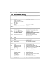
... out Supports HD Audio USB3.0 Asmedia ASM1042 Data transfer rates up to factory default USB2.0 Connector x2 Each connector supports 2 front panel USB2.0 ports 2 Motherboard Manual 1.3 MOTHERBOARD FEATURES SPEC Socket AM3+ AMD 64 Architecture enables 32 and 64 bit CPU AMD Sempron / Phenom II / Athlon II / FX computing processors Supports Hyper...
... out Supports HD Audio USB3.0 Asmedia ASM1042 Data transfer rates up to factory default USB2.0 Connector x2 Each connector supports 2 front panel USB2.0 ports 2 Motherboard Manual 1.3 MOTHERBOARD FEATURES SPEC Socket AM3+ AMD 64 Architecture enables 32 and 64 bit CPU AMD Sempron / Phenom II / Athlon II / FX computing processors Supports Hyper...
Setup Manual
Page 6
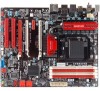
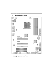
NB_PH_ LE D PH1_ D1 PH3_ D3 PH2_ D2 PH4_ D4 Motherboard Manual 1.5 MOTHERBOARD LAYOUT KB MS1 CP U_FA N1 S PDI F1 ATXP WR2 U SB1 Socke t AM 3+ USB _1394_ ES ATA 1 RJ45USB 1 JUS BV 1 DD R3_A1 DD R3_A2 DD R3_B1 DD R3_B2 ATXP WR1 AUDIO1 LAN Codec A UXP WR1 SY S_FA N2 PEX16_1 AMD 990FX PEX1_1 PEX16_2 PEX16_3 PCI1 JC MOS1 BAT1 AMD SB950 SATA 2 BIOS SATA 1 SATA3 Super I/O F_AU DIO1 C IR1 PCI2 J_COM1 JSP DI FOUT1 S YS _FAN1 F_1394A 1 JFRONT_US B3_1 F_U SB1 JUSBV2 SW_PWR1 F_USB2 SW_RST1 PAN EL1 Note: ■ represents the 1st pin. 4
NB_PH_ LE D PH1_ D1 PH3_ D3 PH2_ D2 PH4_ D4 Motherboard Manual 1.5 MOTHERBOARD LAYOUT KB MS1 CP U_FA N1 S PDI F1 ATXP WR2 U SB1 Socke t AM 3+ USB _1394_ ES ATA 1 RJ45USB 1 JUS BV 1 DD R3_A1 DD R3_A2 DD R3_B1 DD R3_B2 ATXP WR1 AUDIO1 LAN Codec A UXP WR1 SY S_FA N2 PEX16_1 AMD 990FX PEX1_1 PEX16_2 PEX16_3 PCI1 JC MOS1 BAT1 AMD SB950 SATA 2 BIOS SATA 1 SATA3 Super I/O F_AU DIO1 C IR1 PCI2 J_COM1 JSP DI FOUT1 S YS _FAN1 F_1394A 1 JFRONT_US B3_1 F_U SB1 JUSBV2 SW_PWR1 F_USB2 SW_RST1 PAN EL1 Note: ■ represents the 1st pin. 4
Setup Manual
Page 8
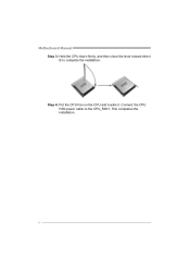
Connect the CPU FAN power cable to complete the installation. Motherboard Manual Step 3: Hold the CPU down firmly, and then close the lever toward direct B to the CPU_FAN1. This completes the installation. 6 Step 4: Put the CPU Fan on the CPU and buckle it.
Connect the CPU FAN power cable to complete the installation. Motherboard Manual Step 3: Hold the CPU down firmly, and then close the lever toward direct B to the CPU_FAN1. This completes the installation. 6 Step 4: Put the CPU Fan on the CPU and buckle it.
Setup Manual
Page 10
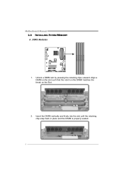
Align a DIMM on the slot such that the notch on the DIMM matches the break on the Slot. 2. DDR 3_A1 DDR 3_A2 DDR 3_B1 DDR 3_B2 Motherboard Manual 2.3 INSTALLING SYSTEM MEMORY A. Unlock a DIMM slot by pressing the retaining clips outward. Insert the DIMM vertically and firmly into the slot until the retaining chip snap back in place and the DIMM is properly seated. 8 DDR3 Modules 1.
Align a DIMM on the slot such that the notch on the DIMM matches the break on the Slot. 2. DDR 3_A1 DDR 3_A2 DDR 3_B1 DDR 3_B2 Motherboard Manual 2.3 INSTALLING SYSTEM MEMORY A. Unlock a DIMM slot by pressing the retaining clips outward. Insert the DIMM vertically and firmly into the slot until the retaining chip snap back in place and the DIMM is properly seated. 8 DDR3 Modules 1.
Setup Manual
Page 12
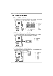
... 3.0 spec and with 5 channels SATA interface, it into Pin 1-2-7-8 of 6.0Gb/s. L SATA2- If CPU power plug is an auxiliary power connection for graphics cards. Motherboard Manual 2.4 CONNECTORS AND SLOTS SATA1~SATA3: Serial ATA Connectors The motherboard has a PCI to CPU power circuit. L SATA3 741 Pin Assignment 1 Ground 2 TX+ 3 TX4 Ground 5 RX6...
... 3.0 spec and with 5 channels SATA interface, it into Pin 1-2-7-8 of 6.0Gb/s. L SATA2- If CPU power plug is an auxiliary power connection for graphics cards. Motherboard Manual 2.4 CONNECTORS AND SLOTS SATA1~SATA3: Serial ATA Connectors The motherboard has a PCI to CPU power circuit. L SATA3 741 Pin Assignment 1 Ground 2 TX+ 3 TX4 Ground 5 RX6...

Setup Manual
Page 14
... PEX1_1 PEX16_2 PEX16_3 12 PCI-Express 2.0 compliant. - PCI-Express 2.0 compliant. - Data transfer bandwidth up to 500MB/s per direction, for an aggregate of 4GB/s totally. Motherboard Manual PEX16_1 ~ PEX16_3: PCI-Express Gen2 x16 Slots - PEX16_1 & PEX16_2 slots are reserved for an aggregate of 16GB/s totally. - Maximum theoretical realized bandwidth of 8GB/s simultaneously...
... PEX1_1 PEX16_2 PEX16_3 12 PCI-Express 2.0 compliant. - PCI-Express 2.0 compliant. - Data transfer bandwidth up to 500MB/s per direction, for an aggregate of 4GB/s totally. Motherboard Manual PEX16_1 ~ PEX16_3: PCI-Express Gen2 x16 Slots - PEX16_1 & PEX16_2 slots are reserved for an aggregate of 16GB/s totally. - Maximum theoretical realized bandwidth of 8GB/s simultaneously...
Setup Manual
Page 16
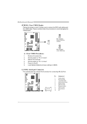
... jumper to "Pin 1-2 close ". 3. Load Optimal Defaults and save settings in CMOS. Please carefully follow the procedures to send 9 Ring indicator 10 NC 1 9 14 Motherboard Manual JCMOS1: Clear CMOS Header Placing the jumper on the AC. 6.
... jumper to "Pin 1-2 close ". 3. Load Optimal Defaults and save settings in CMOS. Please carefully follow the procedures to send 9 Ring indicator 10 NC 1 9 14 Motherboard Manual JCMOS1: Clear CMOS Header Placing the jumper on the AC. 6.
Setup Manual
Page 18
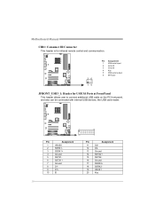
Motherboard Manual CIR1: Consumer IR Connector This header is for infrared remote control and communication. 26 15 Pin Assignment 1 IrDA serial input 2 Ground 3 Ground 4 Key 5 IrDA serial ...
Motherboard Manual CIR1: Consumer IR Connector This header is for infrared remote control and communication. 26 15 Pin Assignment 1 IrDA serial input 2 Ground 3 Ground 4 Key 5 IrDA serial ...

Setup Manual
Page 20
...+ 7 Ground 8 Ground 9 Key 10 NC JUSBV1/JUSBV2: Power Source Headers for USB Ports Pin 1-2 Close: JUSBV1: +5V for USB ports at USB1/USB_1394_ESATA1/ RJ45USB1. Motherboard Manual F_USB1/F_USB2: Headers for USB ports at F_USB1/F_USB2/JFRONT_USB3_1. JUSBV2: +5V for USB 2.0 Ports at F_USB1/F_USB2/JFRONT_USB3_1. JUSBV2: +5V STB for USB ports...
...+ 7 Ground 8 Ground 9 Key 10 NC JUSBV1/JUSBV2: Power Source Headers for USB Ports Pin 1-2 Close: JUSBV1: +5V for USB ports at USB1/USB_1394_ESATA1/ RJ45USB1. Motherboard Manual F_USB1/F_USB2: Headers for USB ports at F_USB1/F_USB2/JFRONT_USB3_1. JUSBV2: +5V for USB 2.0 Ports at F_USB1/F_USB2/JFRONT_USB3_1. JUSBV2: +5V STB for USB ports...

Setup Manual
Page 22
... together in a single computer to activate CFX function. X PEX1_1 X - X: slot not installed) PEX16_2 O X - PEX16_2 O X PEX16_3 O X (O: slot installed; O PEX16_3 O X O - 20 CFX Status PEX16_1 PEX16_1 PEX1_1 - Motherboard Manual CHAPTER 4: CROSSFIREX FUNCTION 4.1 CROSSFIREX INTRODUCTION CrossFireX (also known as ATI CrossFire) is a brand name for ATI Technologies' multi-GPU solution.
... together in a single computer to activate CFX function. X PEX1_1 X - X: slot not installed) PEX16_2 O X - PEX16_2 O X PEX16_3 O X (O: slot installed; O PEX16_3 O X O - 20 CFX Status PEX16_1 PEX16_1 PEX1_1 - Motherboard Manual CHAPTER 4: CROSSFIREX FUNCTION 4.1 CROSSFIREX INTRODUCTION CrossFireX (also known as ATI CrossFire) is a brand name for ATI Technologies' multi-GPU solution.

Setup Manual
Page 24
... a hot-standby copy of data if the active volume or drive is corrupted or becomes unavailable because of automatic backup that eliminates tedious manual backups to the other drive. Drawbacks: Requires 2 drives for small databases or any other application that requires fault tolerance and ...hardware failure. Should one drive. RAID techniques can reside on the same disk or on a second redundant drive in a RAID 1 array system. Motherboard Manual RAID 1: Every read and write is actually carried out in parallel across 2 disk drives in the array. Block 1 Block 2 Block 3 Block 1 Block...
... a hot-standby copy of data if the active volume or drive is corrupted or becomes unavailable because of automatic backup that eliminates tedious manual backups to the other drive. Drawbacks: Requires 2 drives for small databases or any other application that requires fault tolerance and ...hardware failure. Should one drive. RAID techniques can reside on the same disk or on a second redundant drive in a RAID 1 array system. Motherboard Manual RAID 1: Every read and write is actually carried out in parallel across 2 disk drives in the array. Block 1 Block 2 Block 3 Block 1 Block...

Setup Manual
Page 26
... 1 DATA 1 DATA 3 PARITY DATA 7 DATA 9 PARITY Disk 2 DATA 2 PARITY DATA 5 DATA 8 PARITY DATA 11 Disk 3 PARITY DATA 4 DATA 6 PARITY DATA 10 DATA 12 24 Motherboard Manual RAID 5: RAID 5 stripes both data and parity information across all the drives in the array.
... 1 DATA 1 DATA 3 PARITY DATA 7 DATA 9 PARITY Disk 2 DATA 2 PARITY DATA 5 DATA 8 PARITY DATA 11 Disk 3 PARITY DATA 4 DATA 6 PARITY DATA 10 DATA 12 24 Motherboard Manual RAID 5: RAID 5 stripes both data and parity information across all the drives in the array.
Setup Manual
Page 27
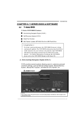
... BIOS information described below in the Setup CD. A. CHAPTER 6: T-SERIES BIOS & SOFTWARE 6.1 T-SERIES BIOS TA990FXE T-Series UEFI BIOS Features Overclocking Navigator Engine (O.N.E.) Self Recovery System (S.R.S) Smart Fan Function BIO-Flasher: Update UEFI BIOS file from this manual is being continuously updated. For further information of Intel CPU perform above overclock setting ideally...
... BIOS information described below in the Setup CD. A. CHAPTER 6: T-SERIES BIOS & SOFTWARE 6.1 T-SERIES BIOS TA990FXE T-Series UEFI BIOS Features Overclocking Navigator Engine (O.N.E.) Self Recovery System (S.R.S) Smart Fan Function BIO-Flasher: Update UEFI BIOS file from this manual is being continuously updated. For further information of Intel CPU perform above overclock setting ideally...

Setup Manual
Page 28
... UEFI BIOS setting, and all overclock settings will protect CPU/System from overheat problem and maintain the system temperature at a safe level. ↓ 26 Motherboard Manual NOTE Overclock is under UEFI BIOS setup, and is always on whenever the system starts up. B. When the system hangs up due to control CPU...
... UEFI BIOS setting, and all overclock settings will protect CPU/System from overheat problem and maintain the system temperature at a safe level. ↓ 26 Motherboard Manual NOTE Overclock is under UEFI BIOS setup, and is always on whenever the system starts up. B. When the system hangs up due to control CPU...
Setup Manual
Page 30
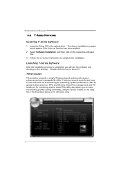
... to the optical drive. Smart-Fan management and PC health are for reference only) 28 Select Software Installation, and then click on the desktop. Motherboard Manual 6.2 T-SERIES SOFTWARE Installing T-Series Software 1. TOverclocker TOverclocker presents a simple Windows-based system performance enhancement and manageability utility. The drivers installation program would appear if the...
... to the optical drive. Smart-Fan management and PC health are for reference only) 28 Select Software Installation, and then click on the desktop. Motherboard Manual 6.2 T-SERIES SOFTWARE Installing T-Series Software 1. TOverclocker TOverclocker presents a simple Windows-based system performance enhancement and manageability utility. The drivers installation program would appear if the...

Setup Manual
Page 32
The HW Monitor tab allows you also can set Modes: V3, V6, V9, V12, V15, AUTO for CPU Smart Fan. 30 Besides, you to monitor hardware voltage, fan speed, and temperature. Motherboard Manual Six Pre-set related values for different overclocking experience.
The HW Monitor tab allows you also can set Modes: V3, V6, V9, V12, V15, AUTO for CPU Smart Fan. 30 Besides, you to monitor hardware voltage, fan speed, and temperature. Motherboard Manual Six Pre-set related values for different overclocking experience.

Setup Manual
Page 34
... consumption are chosen, the system still can keep excellent performance. „ Auto Phase Mode System switches the mode automatically according to save power consumption. Motherboard Manual G.P.U Mode Setting This utility provides five modes, upon your requirements, to improve system performance or to current system loading condition. „ Performance Mode This is...
... consumption are chosen, the system still can keep excellent performance. „ Auto Phase Mode System switches the mode automatically according to save power consumption. Motherboard Manual G.P.U Mode Setting This utility provides five modes, upon your requirements, to improve system performance or to current system loading condition. „ Performance Mode This is...
Setup Manual
Page 36
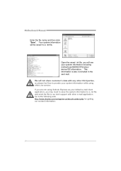
... tech support with any other e-mail application. We will not share customer's data with other third parties, so please feel free to a .txt file. Motherboard Manual Enter the file name and then click "Save". If you may need to save the system information to a .txt file and send the file to...
... tech support with any other e-mail application. We will not share customer's data with other third parties, so please feel free to a .txt file. Motherboard Manual Enter the file name and then click "Save". If you may need to save the system information to a .txt file and send the file to...

