
Setup Manual
Page 1
... to provide reasonable protection against harmful interference in a particular installation. These limits are trademarks of this publication and to make changes to notify any purpose. P31-A7 Setup Manual FCC Information and Copyright This equipment has been tested and found in this user's manual. Further the vendor reserves the right to revise...
... to provide reasonable protection against harmful interference in a particular installation. These limits are trademarks of this publication and to make changes to notify any purpose. P31-A7 Setup Manual FCC Information and Copyright This equipment has been tested and found in this user's manual. Further the vendor reserves the right to revise...

Setup Manual
Page 3
... on the edge, do not try to bend or flex the board. „ Do not leave any unfastened small parts inside the case after installation. P31-A7 CHAPTER 1: INTRODUCTION 1.1 BEFORE YOU START Thank you take the motherboard out from anti-static bag, ground yourself properly by area or your motherboard version. 1 Before...
... on the edge, do not try to bend or flex the board. „ Do not leave any unfastened small parts inside the case after installation. P31-A7 CHAPTER 1: INTRODUCTION 1.1 BEFORE YOU START Thank you take the motherboard out from anti-static bag, ground yourself properly by area or your motherboard version. 1 Before...

Setup Manual
Page 4
... SpeedStep® / Intel Architecture-64 / CPU / Pentium D / Pentium 4 / Celeron D Extended Memory 64 Technology / Virtualization processor Technology FSB Support 533 / 800 / 1066 / 1333 MHz Chipset Intel P31 Intel ICH7 ITE 8712F Environment Control initiatives, Provides the most commonly used legacy Hardware Monitor Controller Super I/O Super I/O functionality.
... SpeedStep® / Intel Architecture-64 / CPU / Pentium D / Pentium 4 / Celeron D Extended Memory 64 Technology / Virtualization processor Technology FSB Support 533 / 800 / 1066 / 1333 MHz Chipset Intel P31 Intel ICH7 ITE 8712F Environment Control initiatives, Provides the most commonly used legacy Hardware Monitor Controller Super I/O Super I/O functionality.

Setup Manual
Page 5
... Keyboard PS/2 Mouse Back Panel Serial Port I/O LAN port USB Port Audio Jack Board Size 190 (W) x 305 (L) mm OS Support Windows 2000 / XP / VISTA P31-A7 SPEC x4 Each connector supports 1 SATA devices x1 Supports front panel facilities x1 Supports front panel audio function x1 Supports CD audio-in function x1... Provide RS-232 Serial connection x1 Connect to RJ-45 ethernet cable x4 Connect to USB devices x3 Provide Audio-In/Out and microphone connection Biostar Reserves the right to the audio port, please use the Line In (blue) and Mic In (Pink) audio jack. 3 However, when connecting ...
... Keyboard PS/2 Mouse Back Panel Serial Port I/O LAN port USB Port Audio Jack Board Size 190 (W) x 305 (L) mm OS Support Windows 2000 / XP / VISTA P31-A7 SPEC x4 Each connector supports 1 SATA devices x1 Supports front panel facilities x1 Supports front panel audio function x1 Supports CD audio-in function x1... Provide RS-232 Serial connection x1 Connect to RJ-45 ethernet cable x4 Connect to USB devices x3 Provide Audio-In/Out and microphone connection Biostar Reserves the right to the audio port, please use the Line In (blue) and Mic In (Pink) audio jack. 3 However, when connecting ...

Setup Manual
Page 6
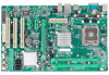
Motherboard Manual 1.5 MOTHERBOARD LAYOUT JKBMS1 LGA775 JCFAN1 JCOM1 JATXPWR1 CPU1 DDR2_A1 DDR2_B1 JUSBV1 JUSB1 JRJ45USB1 JATXPWR2 JAUDIO2 Intel P31 JAUDIOF1 JCDIN1 LAN JSPDIF_OUT1 PEX16_1 Super I/O PEX1_1 JCMOS1 PEX1_2 BAT1 BIOS PCI1 Intel ICH7 SATA1 SATA3 CODEC JPRNT1 PCI2 PCI3 FDD1 SATA2 SATA4 IDE1 JUSBV2 JUSB3 JUSB4 JSFAN1 JPANEL1 Note: ■ represents the 1st pin. 4
Motherboard Manual 1.5 MOTHERBOARD LAYOUT JKBMS1 LGA775 JCFAN1 JCOM1 JATXPWR1 CPU1 DDR2_A1 DDR2_B1 JUSBV1 JUSB1 JRJ45USB1 JATXPWR2 JAUDIO2 Intel P31 JAUDIOF1 JCDIN1 LAN JSPDIF_OUT1 PEX16_1 Super I/O PEX1_1 JCMOS1 PEX1_2 BAT1 BIOS PCI1 Intel ICH7 SATA1 SATA3 CODEC JPRNT1 PCI2 PCI3 FDD1 SATA2 SATA4 IDE1 JUSBV2 JUSB3 JUSB4 JSFAN1 JPANEL1 Note: ■ represents the 1st pin. 4

Setup Manual
Page 7
When the CPU is removed, cover the Pin Cap on the empty socket to a 90-degree angle. 5 Pin Cap Step 1: Pull the socket locking lever out from the socket and then raise the lever up to ensure pin legs won't be damaged. P31-A7 CHAPTER 2: HARDWARE INSTALLATION 2.1 INSTALLING CENTRAL PROCESSING UNIT (CPU) Special Notice: Remove Pin Cap before installation, and make good preservation for future use.
When the CPU is removed, cover the Pin Cap on the empty socket to a 90-degree angle. 5 Pin Cap Step 1: Pull the socket locking lever out from the socket and then raise the lever up to ensure pin legs won't be damaged. P31-A7 CHAPTER 2: HARDWARE INSTALLATION 2.1 INSTALLING CENTRAL PROCESSING UNIT (CPU) Special Notice: Remove Pin Cap before installation, and make good preservation for future use.

Setup Manual
Page 9
... manufacturer. The fan cable and connector may be connected to pin#1. Connect the fan cable to the connector while matching the black wire to GND. 7 P31-A7 2.2 FAN HEADERS These fan headers support cooling-fans built in the computer. JCFAN1: CPU Fan Header 4 Pin Assignment 1 1 Ground 2 +12V 3 FAN RPM rate sense 4 Smart...
... manufacturer. The fan cable and connector may be connected to pin#1. Connect the fan cable to the connector while matching the black wire to GND. 7 P31-A7 2.2 FAN HEADERS These fan headers support cooling-fans built in the computer. JCFAN1: CPU Fan Header 4 Pin Assignment 1 1 Ground 2 +12V 3 FAN RPM rate sense 4 Smart...

Setup Manual
Page 11
... below to the FSB frequency of the motherboard, the memory module must be the same (x8 or x16) D. FSB of the installed CPU. Memory Capacity P31-A7 DIMM Socket Location DDR2_A1 DDR2_B1 DDR Module 256MB/512MB/1GB/2GB 256MB/512MB/1GB/2GB Total Memory Size Max is 4B. C. B. Dual Channel Memory installation...
... below to the FSB frequency of the motherboard, the memory module must be the same (x8 or x16) D. FSB of the installed CPU. Memory Capacity P31-A7 DIMM Socket Location DDR2_A1 DDR2_B1 DDR Module 256MB/512MB/1GB/2GB 256MB/512MB/1GB/2GB Total Memory Size Max is 4B. C. B. Dual Channel Memory installation...

Setup Manual
Page 13
... per direction, for Peripheral Component Interconnect, and it is designated as 32 bits. PCI stands for an aggregate of 500MB/s totally. - PCI1 PCI2 PCI3 11 P31-A7 PEX16_1: PCI-Express x16 Slot - PCI-Express supports a raw bit-rate of 2.5GB/s on the data pins. - 2X bandwidth over the traditional PCI architecture. PCI...
... per direction, for Peripheral Component Interconnect, and it is designated as 32 bits. PCI stands for an aggregate of 500MB/s totally. - PCI1 PCI2 PCI3 11 P31-A7 PEX16_1: PCI-Express x16 Slot - PCI-Express supports a raw bit-rate of 2.5GB/s on the data pins. - 2X bandwidth over the traditional PCI architecture. PCI...

Setup Manual
Page 15
P31-A7 JATXPWR2: ATX Power Source Connector This connector allows user to connect 24-pin power connector on the ATX power supply. 13 1 Pin Assignment 13 +3.3V ...
P31-A7 JATXPWR2: ATX Power Source Connector This connector allows user to connect 24-pin power connector on the ATX power supply. 13 1 Pin Assignment 13 +3.3V ...
Setup Manual
Page 17
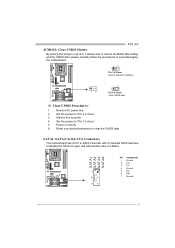
P31-A7 JCMOS1: Clear CMOS Header By placing the jumper on the AC. 6. Reset your desired password or clear the CMOS data. Remove AC power line. 2. SATA1~...
P31-A7 JCMOS1: Clear CMOS Header By placing the jumper on the AC. 6. Reset your desired password or clear the CMOS data. Remove AC power line. 2. SATA1~...

Setup Manual
Page 19
JPRNT1: Printer Port Connector This header allows you to connector printer on the PC. P31-A7 2 1 Pin Assignment 1 -Strobe 2 -ALF 3 Data 0 4 -Error 5 Data 1 6 -Init 7 Data 2 8 -Scltin 9 Data 3 10 Ground 11 Data 4 12 Ground 13 Data 5 25 Pin Assignment 14 Ground 15 Data 6 16 Ground 17 Data 7 18 Ground 19 -ACK 20 Ground 21 Busy 22 Ground 23 PE 24 Ground 25 SCLT 26 Key 17
JPRNT1: Printer Port Connector This header allows you to connector printer on the PC. P31-A7 2 1 Pin Assignment 1 -Strobe 2 -ALF 3 Data 0 4 -Error 5 Data 1 6 -Init 7 Data 2 8 -Scltin 9 Data 3 10 Ground 11 Data 4 12 Ground 13 Data 5 25 Pin Assignment 14 Ground 15 Data 6 16 Ground 17 Data 7 18 Ground 19 -ACK 20 Ground 21 Busy 22 Ground 23 PE 24 Ground 25 SCLT 26 Key 17

Setup Manual
Page 21
P31-A7 4.2 AWARD BIOS BEEP CODE Beep Sound Meaning One long beep followed by two short Video card not found during POST Long beeps every other second ...
P31-A7 4.2 AWARD BIOS BEEP CODE Beep Sound Meaning One long beep followed by two short Video card not found during POST Long beeps every other second ...

Setup Manual
Page 23
P31-A7 This page is intentionally left blank. 21
P31-A7 This page is intentionally left blank. 21