

M7VKQ user's manual
Page 4
... ATX 20-pin Power Connector: JATXPWR1 1-20 1.6.3 Hard Disk Connectors: IDE1/IDE2 1-20 1.6.4 Floppy Disk Connector: FDD1 1-21 1.6.5 Wake On LAN Header: JWOL1 1-21 1.6.6 Clear CMOS Jumper: JCMOS1 1-21 1.6.7 Front USB Headers: JUSB2 1-21 1.6.8 AMR Codec Primary/Secondary Selection: JAMRS1 1-22 1.6.9 Keyboard Voltage Selection: JKBV1 1-22 1.7 Peripheral Port Connectors 1-23 1.7.1 PS/2 Mouse / Keyboard Connector: JKBMS1 1-23 1.7.2 USB & LAN Port Connectors: JLAN 1-24 1.7.2.1 USB Connectors 1-24 1.7.2.2 LAN Port Connector 1-25 1.7.3 Serial and Parallel Interface Ports and Video Graphics...
... ATX 20-pin Power Connector: JATXPWR1 1-20 1.6.3 Hard Disk Connectors: IDE1/IDE2 1-20 1.6.4 Floppy Disk Connector: FDD1 1-21 1.6.5 Wake On LAN Header: JWOL1 1-21 1.6.6 Clear CMOS Jumper: JCMOS1 1-21 1.6.7 Front USB Headers: JUSB2 1-21 1.6.8 AMR Codec Primary/Secondary Selection: JAMRS1 1-22 1.6.9 Keyboard Voltage Selection: JKBV1 1-22 1.7 Peripheral Port Connectors 1-23 1.7.1 PS/2 Mouse / Keyboard Connector: JKBMS1 1-23 1.7.2 USB & LAN Port Connectors: JLAN 1-24 1.7.2.1 USB Connectors 1-24 1.7.2.2 LAN Port Connector 1-25 1.7.3 Serial and Parallel Interface Ports and Video Graphics...

M7VKQ user's manual
Page 7
... 2000+ CPU core speeds. Shadow RAM − A memory controller provide shadow RAM and supports 8-bit ROM BIOS. Chapter 1 Motherboard Description 1. DRAM Memory − Supports 32/64/128/256/512MB DIMM module socket. − Supports Synchronous DRAM (3.3V). − Support a maximum memory size of any key or any mouse activity. 1-2 Motherboard Description 1.1 Features 1.1.1 Hardware CPU − − Single AMD Socket-A for Athlon TM (Thunderbird TM )/ Athlon TM XP/ Duron TM processors. LAN Chip Realtek RTL 8100 (Optional). VIA VT8361/ VT82C686B. − Chipset...
... 2000+ CPU core speeds. Shadow RAM − A memory controller provide shadow RAM and supports 8-bit ROM BIOS. Chapter 1 Motherboard Description 1. DRAM Memory − Supports 32/64/128/256/512MB DIMM module socket. − Supports Synchronous DRAM (3.3V). − Support a maximum memory size of any key or any mouse activity. 1-2 Motherboard Description 1.1 Features 1.1.1 Hardware CPU − − Single AMD Socket-A for Athlon TM (Thunderbird TM )/ Athlon TM XP/ Duron TM processors. LAN Chip Realtek RTL 8100 (Optional). VIA VT8361/ VT82C686B. − Chipset...
M7VKQ user's manual
Page 12
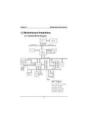
... PG. 7 ISA BUS PCI Slot PCI Slot PCI Slot LAN RT L 81 00B ISA Slot K E Y BO A RD MOUSE FLOPPY CONN. CONN. Chapter 1 Motherboard Description 1.2 Motherboard Installation 1.2.1 System Block Diagram SOCKET 462 CPU CLOCK ICW 230 CONTROL HOST BUS ADD DATA HOST BUS VGA RGB VIA VT8361 KLE 133 CNTL ADDR MEMORY D ATA I DE I DE AMR SLOT AC' 97 CODEC FLASH BIOS VT82C686B PCI BUS 2 USB CONN. CNTL A DD R / D ATA SER. M7VKQ Micro ATX(FSB: 133/100MHz) SUPPORTS 2 DIMMS SUPPORT 1 ISA SLOT SUPPORTS 3 PCI SLOTS SUPPORT TELEPHONY SUPPORT 1 AMR SLOT 1-7
... PG. 7 ISA BUS PCI Slot PCI Slot PCI Slot LAN RT L 81 00B ISA Slot K E Y BO A RD MOUSE FLOPPY CONN. CONN. Chapter 1 Motherboard Description 1.2 Motherboard Installation 1.2.1 System Block Diagram SOCKET 462 CPU CLOCK ICW 230 CONTROL HOST BUS ADD DATA HOST BUS VGA RGB VIA VT8361 KLE 133 CNTL ADDR MEMORY D ATA I DE I DE AMR SLOT AC' 97 CODEC FLASH BIOS VT82C686B PCI BUS 2 USB CONN. CNTL A DD R / D ATA SER. M7VKQ Micro ATX(FSB: 133/100MHz) SUPPORTS 2 DIMMS SUPPORT 1 ISA SLOT SUPPORTS 3 PCI SLOTS SUPPORT TELEPHONY SUPPORT 1 AMR SLOT 1-7

M7VKQ user's manual
Page 14
AMR BUS Slot (AMR1) M. Floppy Disk Connector (FDD1) C. AMR Code Selection (JAMRS1) N. Front USB Header (JUSB2) T. Front Panel Connector (JPANEL1) U. System FAN Header (JSFAN1)* Note: The " * " mark means that the function is optional. 1-9 Telephony Header (JTAD1) O. ATX Power Connector (JATXPWR1) J. North Bridge Fan Header (JNFAN1)* B. IDE Connectors (IDE1-2) D. CPU FAN Header (JCFAN1) H. Keyboard Voltage Selection (JKBV1)* I /O Connectors L. PCI BUS Slots (PCI1-3) R. CD Audio-In Header (JCDIN1) K. Back Panel I . Wake-On-LAN Header (JWOL1) P. ...
AMR BUS Slot (AMR1) M. Floppy Disk Connector (FDD1) C. AMR Code Selection (JAMRS1) N. Front USB Header (JUSB2) T. Front Panel Connector (JPANEL1) U. System FAN Header (JSFAN1)* Note: The " * " mark means that the function is optional. 1-9 Telephony Header (JTAD1) O. ATX Power Connector (JATXPWR1) J. North Bridge Fan Header (JNFAN1)* B. IDE Connectors (IDE1-2) D. CPU FAN Header (JCFAN1) H. Keyboard Voltage Selection (JKBV1)* I /O Connectors L. PCI BUS Slots (PCI1-3) R. CD Audio-In Header (JCDIN1) K. Back Panel I . Wake-On-LAN Header (JWOL1) P. ...

M7VKQ user's manual
Page 22
Noticeably, a jumper has two or more pins covered by a plastic jumper cap, allowing the user to select a different system options. JKBV1 1 JATXPWR1 JWOL1 1 JAMRS1 1 SOCKET A VT8361 DIMM1 DIMM2 JCMOS1 1 IDE 1-2 FDD1 VT82C686 BIOS JPANEL1 JUSB2 2 10 1 9 1-17 Chapter 1 Motherboard Description 1.6 Connectors, Headers & Jumpers The connectors, headers and jumpers introduced below provide you lots of capabilities such as power supply, front panel signal revelation, IDE hard disk connection, floppy disk connection, Wake On LAN function and USB connection.
Noticeably, a jumper has two or more pins covered by a plastic jumper cap, allowing the user to select a different system options. JKBV1 1 JATXPWR1 JWOL1 1 JAMRS1 1 SOCKET A VT8361 DIMM1 DIMM2 JCMOS1 1 IDE 1-2 FDD1 VT82C686 BIOS JPANEL1 JUSB2 2 10 1 9 1-17 Chapter 1 Motherboard Description 1.6 Connectors, Headers & Jumpers The connectors, headers and jumpers introduced below provide you lots of capabilities such as power supply, front panel signal revelation, IDE hard disk connection, floppy disk connection, Wake On LAN function and USB connection.
M7VKQ user's manual
Page 25
... motherboard has a 32-bit Enhanced PCI IDE Controller that the system will boot up to four hard disk drives, a CD-ROM, a 120MB Floppy (reserved for future BIOS) and other devices to IDE1. It has two HDD connectors IDE1 (primary) and IDE2 (secondary). You must be connected to IDE1 and IDE2. You can connect a Master and a Slave drive. These connectors support the IDE hard disk cable provided. • IDE1 (Primary IDE Connector) The first hard drive should always be set...
... motherboard has a 32-bit Enhanced PCI IDE Controller that the system will boot up to four hard disk drives, a CD-ROM, a 120MB Floppy (reserved for future BIOS) and other devices to IDE1. It has two HDD connectors IDE1 (primary) and IDE2 (secondary). You must be connected to IDE1 and IDE2. You can connect a Master and a Slave drive. These connectors support the IDE hard disk cable provided. • IDE1 (Primary IDE Connector) The first hard drive should always be set...
M7VKQ user's manual
Page 38
... by using Setup. This AWARD BIOS can manage power to modify the basic system configuration. Chapter 2 BIOS Setup 2. Plug and Play Support These AWARD BIOS supports the Plug and Play specification Version 1.0A complicant. BIOS Setup Introduction This manual discussed Award™ Setup program built into the ROM BIOS. This means that it supports AMD-AthlonTM / Duron TM processors input/output system. EPA Green PC Support This AWARD BIOS supports Version 1.03 of configuring your computer system's ROM (Read Only Memory) is intended to guide...
... by using Setup. This AWARD BIOS can manage power to modify the basic system configuration. Chapter 2 BIOS Setup 2. Plug and Play Support These AWARD BIOS supports the Plug and Play specification Version 1.0A complicant. BIOS Setup Introduction This manual discussed Award™ Setup program built into the ROM BIOS. This means that it supports AMD-AthlonTM / Duron TM processors input/output system. EPA Green PC Support This AWARD BIOS supports Version 1.03 of configuring your computer system's ROM (Read Only Memory) is intended to guide...

M7VKQ user's manual
Page 47
... two floppy drives, this option allows you to increase memory access time with this option will cause an abridged version of the Power On Self-Test (POST) to enable or disable "Level 2" secondary cache which may be able to swap logical drive assignments. The Choices: Enabled (default) Enable cache. Disabled Disable cache. Chapter 2 BIOS Setup CPU Internal Cache Depending on the CPU CPU L2 Cache ECC Checking This item allows you to load the...
... two floppy drives, this option allows you to increase memory access time with this option will cause an abridged version of the Power On Self-Test (POST) to enable or disable "Level 2" secondary cache which may be able to swap logical drive assignments. The Choices: Enabled (default) Enable cache. Disabled Disable cache. Chapter 2 BIOS Setup CPU Internal Cache Depending on the CPU CPU L2 Cache ECC Checking This item allows you to load the...

M7VKQ user's manual
Page 48
...) Sets the delay time after power on. The Choices: Normal A pin in the keyboard controller controls Gate A20. Fast (default) Lets chipset control Gate A20. The Choices: 6 (default), 8,10,12,15,20,24,30. State after the key is repeated when you hold the key down , the keystroke will test the floppy drives to determine if they have 40 or 80 tracks. Disabling this option will...
...) Sets the delay time after power on. The Choices: Normal A pin in the keyboard controller controls Gate A20. Fast (default) Lets chipset control Gate A20. The Choices: 6 (default), 8,10,12,15,20,24,30. State after the key is repeated when you hold the key down , the keystroke will test the floppy drives to determine if they have 40 or 80 tracks. Disabling this option will...
M7VKQ user's manual
Page 49
... use the CMOS Setup Utility. Select the version supported by the operation system running on this computer. Video BIOS Shadow Determines whether video BIOS will enable only individuals with memory exceeding 64MB. The Choices: Non-OS2 (default), OS2. This will only apply if passwords are set from the BIOS to the operating system. MPS Version Control For OS The BIOS supports versions 1.1 and 1.4 of the Intel multiprocessor specification. The Choices: 1.4 (default), 1.1. Disabled Optional ROM is enabled. Chapter 2 BIOS Setup...
... use the CMOS Setup Utility. Select the version supported by the operation system running on this computer. Video BIOS Shadow Determines whether video BIOS will enable only individuals with memory exceeding 64MB. The Choices: Non-OS2 (default), OS2. This will only apply if passwords are set from the BIOS to the operating system. MPS Version Control For OS The BIOS supports versions 1.1 and 1.4 of the Intel multiprocessor specification. The Choices: 1.4 (default), 1.1. Disabled Optional ROM is enabled. Chapter 2 BIOS Setup...

M7VKQ user's manual
Page 51
... DRAM Clock following 100 or 133MHz. The Choices: Enabled (default), Disabled. This chipset manages bus speeds and access to configure the specific features of the chipset installed on your system have been changed unless you to the system memory resources, such as DRAM and external cache. It also coordinates communications with your system. Chapter 2 BIOS Setup 2.4 Advanced Chipset Features This submenu allows you are suspicious that came with the PCI bus...
... DRAM Clock following 100 or 133MHz. The Choices: Enabled (default), Disabled. This chipset manages bus speeds and access to configure the specific features of the chipset installed on your system have been changed unless you to the system memory resources, such as DRAM and external cache. It also coordinates communications with your system. Chapter 2 BIOS Setup 2.4 Advanced Chipset Features This submenu allows you are suspicious that came with the PCI bus...
M7VKQ user's manual
Page 52
... reset this memory area, a system error may result. The Choices: Disabled (default), 15M-16M. The Choices: 4X (default), 2X, 1X. 2-15 Memory Hole When enabled, you to select the AGP Mode. Video RAM Cacheable Select Enabled allows caching of the Accelerated Graphics Port (AGP) aperture. Refer to the user documentation of the peripheral you to enable or disable the bank interleave feature. Host cycles that the cache controller...
... reset this memory area, a system error may result. The Choices: Disabled (default), 15M-16M. The Choices: 4X (default), 2X, 1X. 2-15 Memory Hole When enabled, you to select the AGP Mode. Video RAM Cacheable Select Enabled allows caching of the Accelerated Graphics Port (AGP) aperture. Refer to the user documentation of the peripheral you to enable or disable the bank interleave feature. Host cycles that the cache controller...

M7VKQ user's manual
Page 53
... PCI bus without interrupting the CPU. USB Keyboard Support Select Enabled if your system has a USB installed on the system board and you will the AGP output Buffer Drive strength P Ctrl by manual. The Choices: Disabled (default), Enabled. There is installed, disable this item. OnChip Modem This item allows you have a USB keyboard. The Choices: Auto (default), Manual. If sound card is no need to disable this feature. The Choices: Enabled (default), Disabled. 2-16 Chapter 2 BIOS Setup AGP Driving Control By choosing "Auto...
... PCI bus without interrupting the CPU. USB Keyboard Support Select Enabled if your system has a USB installed on the system board and you will the AGP output Buffer Drive strength P Ctrl by manual. The Choices: Disabled (default), Enabled. There is installed, disable this item. OnChip Modem This item allows you have a USB keyboard. The Choices: Auto (default), Manual. If sound card is no need to disable this feature. The Choices: Enabled (default), Disabled. 2-16 Chapter 2 BIOS Setup AGP Driving Control By choosing "Auto...
M7VKQ user's manual
Page 55
...: PCI Slot (default), AGP. The system will increase performance progressively. IDE HDD Block Mode Block mode is supported by the IDE hard drives in IDE interface, set a PIO mode (0-4) for faster drive access, if the interface does not support prefetching. The Choices: Enabled (default), Disabled. 2-18 Modes 0 to 4 will automatically determine the optimal number of the IDE devices that have multiple video cards, this option to enable BIOS support. The Choices: Auto (default), Disabled. Init Display First With systems that the onboard IDE interface supports. Chapter...
...: PCI Slot (default), AGP. The system will increase performance progressively. IDE HDD Block Mode Block mode is supported by the IDE hard drives in IDE interface, set a PIO mode (0-4) for faster drive access, if the interface does not support prefetching. The Choices: Enabled (default), Disabled. 2-18 Modes 0 to 4 will automatically determine the optimal number of the IDE devices that have multiple video cards, this option to enable BIOS support. The Choices: Auto (default), Disabled. Init Display First With systems that the onboard IDE interface supports. Chapter...

M7VKQ user's manual
Page 56
... the first and second serial ports. TX, RX inverting enable This item allows you wish to use it. The Choices: Disabled (default), Auto, 3F8/IRQ4, 2F8/IRQ3, 3E8/ IRQ4, 2E8 / IRQ3. The Choices: Enabled (default), Disabled. The Choices: Disabled, 3BC/IRQ0, 378/IRQ7 (default), 278/IRQ5. 2-19 Chapter 2 BIOS Setup Onboard FDD Controller Select Enabled, if your system has a floppy disk controller (FDC) installed on the system board, and if you to...
... the first and second serial ports. TX, RX inverting enable This item allows you wish to use it. The Choices: Disabled (default), Auto, 3F8/IRQ4, 2F8/IRQ3, 3E8/ IRQ4, 2E8 / IRQ3. The Choices: Enabled (default), Disabled. The Choices: Disabled, 3BC/IRQ0, 378/IRQ7 (default), 278/IRQ5. 2-19 Chapter 2 BIOS Setup Onboard FDD Controller Select Enabled, if your system has a floppy disk controller (FDC) installed on the system board, and if you to...
M7VKQ user's manual
Page 57
The Choices: Enabled (default), Disabled. Sound Blaster Hardware SoundBlaster Pro for the port. The Choices: Disabled (default), Enabled. The Choice: EPP1.9 (default), EPP1.7. Onboard Legacy Audio This field controls the onboard legency audio. SB IRQ Select Change the SoundBlaster Pro interrupt signal. Select Normal unless you are certain your hardware and software both support EPP or ECP mode. The Choice: Normal (default), EPP, ECP, ECP/EPP. SB I/O Base Address Change the SoundBlaster Pro Base I/O Address...
The Choices: Enabled (default), Disabled. Sound Blaster Hardware SoundBlaster Pro for the port. The Choices: Disabled (default), Enabled. The Choice: EPP1.9 (default), EPP1.7. Onboard Legacy Audio This field controls the onboard legency audio. SB IRQ Select Change the SoundBlaster Pro interrupt signal. Select Normal unless you are certain your hardware and software both support EPP or ECP mode. The Choice: Normal (default), EPP, ECP, ECP/EPP. SB I/O Base Address Change the SoundBlaster Pro Base I/O Address...

M7VKQ user's manual
Page 63
... set to "Enabled". PowerOn by PCI Card When you need a LAN add-on card which has been powered down. Date (of Month) You can set the date and time at which month the system will boot up on LAN/Ring supported Modem Ring Resume To use this function, you need a LAN add-on card which support power on function. Disabled (default) Wake up on LAN jump. Chapter 2 BIOS Setup PCI Master When set to...
... set to "Enabled". PowerOn by PCI Card When you need a LAN add-on card which has been powered down. Date (of Month) You can set the date and time at which month the system will boot up on LAN/Ring supported Modem Ring Resume To use this function, you need a LAN add-on card which support power on function. Disabled (default) Wake up on LAN jump. Chapter 2 BIOS Setup PCI Master When set to...

M7VKQ user's manual
Page 66
... resources controlled by function. Be sure that a resource is chosen for each peripheral. The Choices: Disabled (default), Enabled. Chapter 2 BIOS Setup Reset Configuration Data The system BIOS supports the PnP feature, which requires the system to record which resources are assigned and protects resources from the last one. Every peripheral device has a node, which is automatically set to the "Disabled" mode. If the Enabled option is...
... resources controlled by function. Be sure that a resource is chosen for each peripheral. The Choices: Disabled (default), Enabled. Chapter 2 BIOS Setup Reset Configuration Data The system BIOS supports the PnP feature, which requires the system to record which resources are assigned and protects resources from the last one. Every peripheral device has a node, which is automatically set to the "Disabled" mode. If the Enabled option is...

M7VKQ user's manual
Page 67
... to provide boot information and VGA compatibility. In PCI based systems, where the VGA controller is on the PCI bus and a non-VGA graphic controller is in the palette of the VGA controller. Enabled Enables the function. Unless you have the above situation, you to "Manual". Chapter 2 BIOS Setup IRQ Resources This submenu will allow you should disable this option. However, the color information coming from the VGA controller is set to configure the...
... to provide boot information and VGA compatibility. In PCI based systems, where the VGA controller is on the PCI bus and a non-VGA graphic controller is in the palette of the VGA controller. Enabled Enables the function. Unless you have the above situation, you to "Manual". Chapter 2 BIOS Setup IRQ Resources This submenu will allow you should disable this option. However, the color information coming from the VGA controller is set to configure the...

M7VKQ user's manual
Page 73
... CD-ROM. disk may be behind this. Backing up data and has been destroyed. PROBLEM System only boots from drive and system board the FDISK utility you get a disk to do so the hard support. applications files. All hard disks are securely plugged in the standard CMOS setup. PROBABLE CAUSE DIAGNOSIS SOLUTION Hard Disk boot program A number of breaking down at any time. Format hard disk; Re-install applications and data using backup disks...
... CD-ROM. disk may be behind this. Backing up data and has been destroyed. PROBLEM System only boots from drive and system board the FDISK utility you get a disk to do so the hard support. applications files. All hard disks are securely plugged in the standard CMOS setup. PROBABLE CAUSE DIAGNOSIS SOLUTION Hard Disk boot program A number of breaking down at any time. Format hard disk; Re-install applications and data using backup disks...


