

M7VKH user's manual
Page 3
... 1-2 1.1.1 Hardware 1-2 1.1.2 Software 1-5 1.1.3 Attachments 1-5 1.2 Motherboard Installation 1-6 1.2.1 Layout of Motherboard 1-6 1.3 Motherboard Quick Reference 1-7 1.3.1 Front Panel Headers (JPANEL1 / JPANEL2 1-8 1.3.2 Floppy Disk Connector (FDD1 1-10 1.3.3 Hard Disk Connectors (IDE1/IDE2 1-10 1.3.4 ATX 20-pin Power Connector (JATXPWR1 1-11 1.4 ...
... 1-2 1.1.1 Hardware 1-2 1.1.2 Software 1-5 1.1.3 Attachments 1-5 1.2 Motherboard Installation 1-6 1.2.1 Layout of Motherboard 1-6 1.3 Motherboard Quick Reference 1-7 1.3.1 Front Panel Headers (JPANEL1 / JPANEL2 1-8 1.3.2 Floppy Disk Connector (FDD1 1-10 1.3.3 Hard Disk Connectors (IDE1/IDE2 1-10 1.3.4 ATX 20-pin Power Connector (JATXPWR1 1-11 1.4 ...
M7VKH user's manual
Page 6
It is ideal for operation, and how to help you will find relevant topics. Inside you start using this product! Chapter 1 Motherboard Description Introduction System Overview Thanks for buying this product as quickly and smoothly as possible. The mainboard, a AMD AthlonTM and DuronTM processor based PC Micro ...
It is ideal for operation, and how to help you will find relevant topics. Inside you start using this product! Chapter 1 Motherboard Description Introduction System Overview Thanks for buying this product as quickly and smoothly as possible. The mainboard, a AMD AthlonTM and DuronTM processor based PC Micro ...
M7VKH user's manual
Page 7
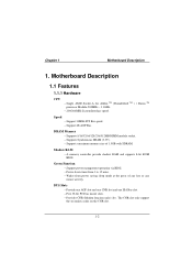
Motherboard Description 1.1 Features 1.1.1 Hardware CPU − Single AMD Socket-A for Athlon TM (Thunderbird TM ) / Duron TM processor Module-500MHz ~ 1.3GHz. − 200/266MHz System Interface speed. ... via BIOS. − Power down timer from 1 to 15 mins. − Wakes from power saving sleep mode at the press of 1.5GB with SDRAM. Chapter 1 Motherboard Description 1. BUS Slots − Provide one AGP slot and one CNR slot and one ISA Bus slot. − Five 32-bit PCI bus master slots...
Motherboard Description 1.1 Features 1.1.1 Hardware CPU − Single AMD Socket-A for Athlon TM (Thunderbird TM ) / Duron TM processor Module-500MHz ~ 1.3GHz. − 200/266MHz System Interface speed. ... via BIOS. − Power down timer from 1 to 15 mins. − Wakes from power saving sleep mode at the press of 1.5GB with SDRAM. Chapter 1 Motherboard Description 1. BUS Slots − Provide one AGP slot and one CNR slot and one ISA Bus slot. − Five 32-bit PCI bus master slots...
M7VKH user's manual
Page 8
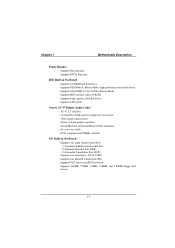
... 10 band graphic equalizer. − Sound Blaster® and Sound Blaster Pro® emulation. − 64-voice wavetable. − PC99 complaint and WHQL certified. Chapter 1 Motherboard Description Flash Memory − Supports flash memory. − Supports ESCD Function. I/O Built-in On Board − Supports four IDE hard disk drives. − Supports PIO...
... 10 band graphic equalizer. − Sound Blaster® and Sound Blaster Pro® emulation. − 64-voice wavetable. − PC99 complaint and WHQL certified. Chapter 1 Motherboard Description Flash Memory − Supports flash memory. − Supports ESCD Function. I/O Built-in On Board − Supports four IDE hard disk drives. − Supports PIO...
M7VKH user's manual
Page 9
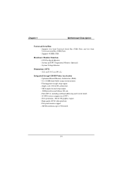
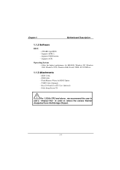
... generation, 128-bit 2D graphics engine. − High quality DVD video playback. − Flat panel monitor support. − 2D/3D resolutions up to 1920x1440. 1-4 Chapter 1 Motherboard Description Universal Serial Bus − Supports two back Universal Serial Bus (USB) Ports and two front Universal serial Bus (USB) Ports. − Supports 48 MHz...
... generation, 128-bit 2D graphics engine. − High quality DVD video playback. − Flat panel monitor support. − 2D/3D resolutions up to 1920x1440. 1-4 Chapter 1 Motherboard Description Universal Serial Bus − Supports two back Universal Serial Bus (USB) Ports and two front Universal serial Bus (USB) Ports. − Supports 48 MHz...
M7VKH user's manual
Page 10
... Cable. − Flash Memory Writer for BIOS Update. − USB2 Cable (Optional). − Rear I/O Panel for ATX Case (Optional). − Fully Setup Driver CD. Chapter 1 Motherboard Description 1.1.2 Software BIOS − AWARD legal BIOS. − Supports APM1.2. − Supports USB Function. − Supports ACPI.
... Cable. − Flash Memory Writer for BIOS Update. − USB2 Cable (Optional). − Rear I/O Panel for ATX Case (Optional). − Fully Setup Driver CD. Chapter 1 Motherboard Description 1.1.2 Software BIOS − AWARD legal BIOS. − Supports APM1.2. − Supports USB Function. − Supports ACPI.

M7VKH user's manual
Page 11
Chapter 1 Motherboard Description 1.2 Motherboard Installation 1.2.1 Layout of Motherboard Model No.M7VKH 1-6
Chapter 1 Motherboard Description 1.2 Motherboard Installation 1.2.1 Layout of Motherboard Model No.M7VKH 1-6

M7VKH user's manual
Page 12
... function is optional. 1-7 Wake-On MODEM Header (JWOM1*) B. CD Audio-In Headers (JCDIN1-2) O. IDE Connectors (IDE1-2) F. CPU Frequency Selection (JCLK1) H. CPU Fan Header (JCFAN1) K. Chapter 1 Motherboard Description 1.3 Motherboard Quick Reference T SR P N M L K J U I . AUX Audio-In Header (JAUX1*) N. PCI BUS Slots (PCI1-5) R. DIMMs (DIMM1-3) J. Front USB Header (JUSB2) W. FDD Connector (FDD1) E. Back Panel I/O Connectors...
... function is optional. 1-7 Wake-On MODEM Header (JWOM1*) B. CD Audio-In Headers (JCDIN1-2) O. IDE Connectors (IDE1-2) F. CPU Frequency Selection (JCLK1) H. CPU Fan Header (JCFAN1) K. Chapter 1 Motherboard Description 1.3 Motherboard Quick Reference T SR P N M L K J U I . AUX Audio-In Header (JAUX1*) N. PCI BUS Slots (PCI1-5) R. DIMMs (DIMM1-3) J. Front USB Header (JUSB2) W. FDD Connector (FDD1) E. Back Panel I/O Connectors...

M7VKH user's manual
Page 13
Chapter 1 Motherboard Description 1.3.1 Front Panel Headers (JPANEL1 / JPANEL2) JPANEL1 JPANEL2 V G NC PWR-LED PWR-LED PWR 2 82 1 71 SPK HLED RST SLP NC V NC 18 17 IR ...
Chapter 1 Motherboard Description 1.3.1 Front Panel Headers (JPANEL1 / JPANEL2) JPANEL1 JPANEL2 V G NC PWR-LED PWR-LED PWR 2 82 1 71 SPK HLED RST SLP NC V NC 18 17 IR ...
M7VKH user's manual
Page 14
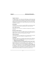
... After the IrDA interface is configured, files can be transferred from or to the motherboard at the front panel connector. Chapter 1 Motherboard Description Speaker Connector An offboard speaker can be installed on the motherboard as laptops, PDAs, and printers using the BIOS inactivity timer feature The 2-pin ... error beep code information during the Power On Self-Test when the computer cannot use the video interface. The speaker is closed, the motherboard resets and runs the POST. For the LED to function properly, an IDE drive must be connected to a hard drive. To reactivate...
... After the IrDA interface is configured, files can be transferred from or to the motherboard at the front panel connector. Chapter 1 Motherboard Description Speaker Connector An offboard speaker can be installed on the motherboard as laptops, PDAs, and printers using the BIOS inactivity timer feature The 2-pin ... error beep code information during the Power On Self-Test when the computer cannot use the video interface. The speaker is closed, the motherboard resets and runs the POST. For the LED to function properly, an IDE drive must be connected to a hard drive. To reactivate...
M7VKH user's manual
Page 15
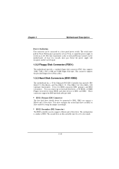
... can also support a Master and a Slave drive. This connector supports the provided floppy drive ribbon cables. 1.3.3 Hard Disk Connectors (IDE1/IDE2) The motherboard has a 32-bit Enhanced PCI IDE Controller that supports 360K, 720K, 1.2M, 1.44M and 2.88M floppy disk types. IDE1 can connect a Master... and other devices to IDE1 and IDE2. The configuration is due to internal debounce circuitry on or off signal. 1.3.2 Floppy Disk Connector (FDD1) The motherboard provides a standard floppy disk connector (FDC) that provides PIO Mode 0~4, Bus Master, and Ultra DMA / 33, Ultra DMA / 66, Ultra DMA ...
... can also support a Master and a Slave drive. This connector supports the provided floppy drive ribbon cables. 1.3.3 Hard Disk Connectors (IDE1/IDE2) The motherboard has a 32-bit Enhanced PCI IDE Controller that supports 360K, 720K, 1.2M, 1.44M and 2.88M floppy disk types. IDE1 can connect a Master... and other devices to IDE1 and IDE2. The configuration is due to internal debounce circuitry on or off signal. 1.3.2 Floppy Disk Connector (FDD1) The motherboard provides a standard floppy disk connector (FDC) that provides PIO Mode 0~4, Bus Master, and Ultra DMA / 33, Ultra DMA / 66, Ultra DMA ...
M7VKH user's manual
Page 16
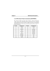
... power connector supports instant power-on functionality, which means that the system will boot up instantly when the power connector is inserted on -board. Chapter 1 Motherboard Description 1.3.4 ATX 20-pin Power Connector (JATXPWR1) This connector supports the power button on the board. Pin No. 1 2 3 4 5 6 7 8 9 10 Assignment +3.3V +3.3V Ground +5V Ground... Ground -5V +5V +5V 1-11 Using the ATX power supply, functions such as Modem Ring Wake-Up and Soft Power Off are supported on this motherboard.
... power connector supports instant power-on functionality, which means that the system will boot up instantly when the power connector is inserted on -board. Chapter 1 Motherboard Description 1.3.4 ATX 20-pin Power Connector (JATXPWR1) This connector supports the power button on the board. Pin No. 1 2 3 4 5 6 7 8 9 10 Assignment +3.3V +3.3V Ground +5V Ground... Ground -5V +5V +5V 1-11 Using the ATX power supply, functions such as Modem Ring Wake-Up and Soft Power Off are supported on this motherboard.

M7VKH user's manual
Page 17
... JUSB1 CN2 Parallel U14 Game Port PS/2 USB Keyboard COM1 CN1 VGA1 CN3 Speaker Line Mic out in in 1.4.1 PS/2 Mouse / Keyboard CONN.: JKBMS1 The motherboard provides a standard PS/2 mouse / Keyboard mini DIN connector for attaching a PS/2 mouse. You can plug a PS/2 mouse / Keyboard directly into this connector. The connector location...
... JUSB1 CN2 Parallel U14 Game Port PS/2 USB Keyboard COM1 CN1 VGA1 CN3 Speaker Line Mic out in in 1.4.1 PS/2 Mouse / Keyboard CONN.: JKBMS1 The motherboard provides a standard PS/2 mouse / Keyboard mini DIN connector for attaching a PS/2 mouse. You can plug a PS/2 mouse / Keyboard directly into this connector. The connector location...

M7VKH user's manual
Page 18
Assignment 1 +5 V 2 USBP0- [USBP1-] 3 USBP0+ [USBP1+] 4 Ground Signal names in brackets ([]) are for attaching USB devices such as: keyboard, mouse and other USB device. Chapter 1 Motherboard Description PS/2 Mouse / Keyboard Connectors Pin No. 1 2 3 4 5 6 Assignment Data No connection Ground +5 V Clock No connection 1.4.2 USB Connector: JUSB1 The motherboard provides a OHCI (Open Host Controller Interface) Universal Serial Bus Roots for USB Port 1. 1-13 JUSB1 USB 12 34 1234 Stacked USB Connector Pin No.
Assignment 1 +5 V 2 USBP0- [USBP1-] 3 USBP0+ [USBP1+] 4 Ground Signal names in brackets ([]) are for attaching USB devices such as: keyboard, mouse and other USB device. Chapter 1 Motherboard Description PS/2 Mouse / Keyboard Connectors Pin No. 1 2 3 4 5 6 Assignment Data No connection Ground +5 V Clock No connection 1.4.2 USB Connector: JUSB1 The motherboard provides a OHCI (Open Host Controller Interface) Universal Serial Bus Roots for USB Port 1. 1-13 JUSB1 USB 12 34 1234 Stacked USB Connector Pin No.

M7VKH user's manual
Page 19
Assignment Pin No. Chapter 1 Motherboard Description 1.4.3 Monitor Connector: JVGA1 This motherboard has built in video facilities. Your monitor will attach directly to JVGA1 connector on the motherboard. 5 1 15 11 JVGA1 Pin No. Assignment 1 Red 2 Green 3 Blue 4 +5V 5 Ground 6 Ground 7 Ground 8 Ground 9 +5V 10 Ground 11 +5V 12 DDC/Data 13 HSYNC 14 VSYNC 15 DDC/CLK 1-14
Assignment Pin No. Chapter 1 Motherboard Description 1.4.3 Monitor Connector: JVGA1 This motherboard has built in video facilities. Your monitor will attach directly to JVGA1 connector on the motherboard. 5 1 15 11 JVGA1 Pin No. Assignment 1 Red 2 Green 3 Blue 4 +5V 5 Ground 6 Ground 7 Ground 8 Ground 9 +5V 10 Ground 11 +5V 12 DDC/Data 13 HSYNC 14 VSYNC 15 DDC/CLK 1-14

M7VKH user's manual
Page 20
Chapter 1 Motherboard Description 1.4.4 Front USB Header: JUSB2 JUSB2 2 10 19 Pin No. Assignment 1 +5V 2 Ground 3 USBP2- 4 Ground 5 USBP2+ 6 USBP3+ 7 Ground 8 USBP3- 9 Ground 10 +5V 1-15 Assignment Pin No.
Chapter 1 Motherboard Description 1.4.4 Front USB Header: JUSB2 JUSB2 2 10 19 Pin No. Assignment 1 +5V 2 Ground 3 USBP2- 4 Ground 5 USBP2+ 6 USBP3+ 7 Ground 8 USBP3- 9 Ground 10 +5V 1-15 Assignment Pin No.

M7VKH user's manual
Page 21
... port. The serial port on this chapter. Some older computer systems and peripherals used to be explained in this system has one parallel port. Chapter 1 Motherboard Description 1.5 Serial and Parallel Interface Ports This system comes equipped with only one 25-pin connector. The Serial Interface: CN1 The serial interface port is...
... port. The serial port on this chapter. Some older computer systems and peripherals used to be explained in this system has one parallel port. Chapter 1 Motherboard Description 1.5 Serial and Parallel Interface Ports This system comes equipped with only one 25-pin connector. The Serial Interface: CN1 The serial interface port is...

M7VKH user's manual
Page 22
... information can be used in many ways, and it may be used when configuring certain software programs to become familiar with the serial port. Chapter 1 Motherboard Description Connectivity The serial port can be necessary to work with the pinout diagram. Signal DCD RX TX DTR GND DSR RTS CTS RI Name...
... information can be used in many ways, and it may be used when configuring certain software programs to become familiar with the serial port. Chapter 1 Motherboard Description Connectivity The serial port can be necessary to work with the pinout diagram. Signal DCD RX TX DTR GND DSR RTS CTS RI Name...

M7VKH user's manual
Page 23
..., a special adapter called a "Null Modem" is called "DTE" (Data Terminal Equipment) and the other manufacturers do not use one problem in particular may arise. Chapter 1 Motherboard Description The Serial Interface Port-II: JCOM2 (Optional) 2 10 Signal DCD RX TX DTR GND DSR RTS CTS RI 1 9 Name Data Carrier Detect Receive Data...
..., a special adapter called a "Null Modem" is called "DTE" (Data Terminal Equipment) and the other manufacturers do not use one problem in particular may arise. Chapter 1 Motherboard Description The Serial Interface Port-II: JCOM2 (Optional) 2 10 Signal DCD RX TX DTR GND DSR RTS CTS RI 1 9 Name Data Carrier Detect Receive Data...
M7VKH user's manual
Page 24
... you on the computer are available. COM1) and the scanner must have installed an internal modem, be assigned to assign only one COM port (i.e. Chapter 1 Motherboard Description signals to another device. The manuals that have completed the installation of a serial port, use a diagnostic program to send messages. If you encounter a communication...
... you on the computer are available. COM1) and the scanner must have installed an internal modem, be assigned to assign only one COM port (i.e. Chapter 1 Motherboard Description signals to another device. The manuals that have completed the installation of a serial port, use a diagnostic program to send messages. If you encounter a communication...

