
Setup Manual
Page 1
... no representations or warranties with respect to provide reasonable protection against harmful interference in a particular installation. The content of this user's manual. All the brand and product names are designed to the contents here and specially disclaims any implied warranties of their respective companies. ...CE, 2006/95/CE e 1999/05/CE quando ad esso applicabili Short Declaration of the FCC Rules. H61MGB/H61MLB/H61MHB Setup Manual FCC Information and Copyright This equipment has been tested and found in this publication, in part or in whole, is not ...
... no representations or warranties with respect to provide reasonable protection against harmful interference in a particular installation. The content of this user's manual. All the brand and product names are designed to the contents here and specially disclaims any implied warranties of their respective companies. ...CE, 2006/95/CE e 1999/05/CE quando ad esso applicabili Short Declaration of the FCC Rules. H61MGB/H61MLB/H61MHB Setup Manual FCC Information and Copyright This equipment has been tested and found in this publication, in part or in whole, is not ...
Setup Manual
Page 3
... a dry and stable working environment with sufficient lighting. „ Always disconnect the computer from power outlet before operation. „ Before you for ATX Case X 1 User's Manual X 1 Fully Setup Driver DVD X 1 USB 2.0 Cable X1 (optional) Serial ATA Power Cable X 1 (optional) Note: The package contents may be different due to 45 degrees Celsius...
... a dry and stable working environment with sufficient lighting. „ Always disconnect the computer from power outlet before operation. „ Before you for ATX Case X 1 User's Manual X 1 Fully Setup Driver DVD X 1 USB 2.0 Cable X1 (optional) Serial ATA Power Cable X 1 (optional) Note: The package contents may be different due to 45 degrees Celsius...

Setup Manual
Page 4
... PCI Slot x2 PCI Slot x2 On Board Printer Port Connector x1 Printer Port Connector x1 Serial Port Connector x1 Serial Port Connector x1 2 Motherboard Manual 1.3 MOTHERBOARD FEATURES H61MGB / H61MLB H61MHB Socket 1155 Socket 1155 Intel Core i7 / i5 / i3/ Pentium processor Intel Core i7 / i5 / i3/ Pentium processor Supports Execute...
... PCI Slot x2 PCI Slot x2 On Board Printer Port Connector x1 Printer Port Connector x1 Serial Port Connector x1 Serial Port Connector x1 2 Motherboard Manual 1.3 MOTHERBOARD FEATURES H61MGB / H61MLB H61MHB Socket 1155 Socket 1155 Intel Core i7 / i5 / i3/ Pentium processor Intel Core i7 / i5 / i3/ Pentium processor Supports Execute...

Setup Manual
Page 6
Motherboard Manual Display Devices Enabled VGA + HDMI VGA + DVI-D HDMI + DVI-D O O O 4
Motherboard Manual Display Devices Enabled VGA + HDMI VGA + DVI-D HDMI + DVI-D O O O 4

Setup Manual
Page 8
Please refer below instruction to ensure pin legs won't be damaged. 2. Remove Pin Cap before installation, and make good preservation for future use. Step 2: Remove the Pin Cap. 6 When the CPU is removed, cover the Pin Cap on the empty socket to remove the pin cap. The motherboard might equip with two different types of pin cap. Motherboard Manual CHAPTER 2: HARDWARE INSTALLATION 2.1 INSTALLING CENTRAL PROCESSING UNIT (CPU) Notice: 1. Step 1: Pull the socket locking lever out from the socket then raise the lever and load plate to the fully open position.
Please refer below instruction to ensure pin legs won't be damaged. 2. Remove Pin Cap before installation, and make good preservation for future use. Step 2: Remove the Pin Cap. 6 When the CPU is removed, cover the Pin Cap on the empty socket to remove the pin cap. The motherboard might equip with two different types of pin cap. Motherboard Manual CHAPTER 2: HARDWARE INSTALLATION 2.1 INSTALLING CENTRAL PROCESSING UNIT (CPU) Notice: 1. Step 1: Pull the socket locking lever out from the socket then raise the lever and load plate to the fully open position.

Setup Manual
Page 10
SYS_FAN1, 3-pin head one. Motherboard Manual 2.2 FAN HEADERS These fan headers support cooling-fans built in the computer. CPU_FAN1: CPU Fan Header 1 4 Pin Assignment 1 Ground 2 Power 3 FAN RPM rate sense 4 Smart ...
SYS_FAN1, 3-pin head one. Motherboard Manual 2.2 FAN HEADERS These fan headers support cooling-fans built in the computer. CPU_FAN1: CPU Fan Header 1 4 Pin Assignment 1 Ground 2 Power 3 FAN RPM rate sense 4 Smart ...
Setup Manual
Page 12
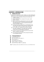
Dual Channel Status DDR3_A1 DDR3_B1 Disabled O X Disabled X O Enabled O O (O means memory installed; Motherboard Manual B. Memory Capacity DIMM Socket Location DDR3_A1 DDR3_B1 DDR3 Module 512MB/1GB/2GB/4GB/8GB 512MB/1GB/2GB/4GB/8GB Total Memory Size Max is 16GB. C. X, not installed.) The DRAM bus width of the same density in pairs, shown in the table. Dual Channel Memory Installation Please refer to the following requirements to activate Dual Channel function: Install memory module of the memory module must be the same(x8 or x16) 10
Dual Channel Status DDR3_A1 DDR3_B1 Disabled O X Disabled X O Enabled O O (O means memory installed; Motherboard Manual B. Memory Capacity DIMM Socket Location DDR3_A1 DDR3_B1 DDR3 Module 512MB/1GB/2GB/4GB/8GB 512MB/1GB/2GB/4GB/8GB Total Memory Size Max is 16GB. C. X, not installed.) The DRAM bus width of the same density in pairs, shown in the table. Dual Channel Memory Installation Please refer to the following requirements to activate Dual Channel function: Install memory module of the memory module must be the same(x8 or x16) 10

Setup Manual
Page 14
Motherboard Manual ATXPWR1: ATX Power Source Connector This connector is for 24-pin power connector on the ATX power supply. 12 24 1 13 Pin Assignment 13 +3.3V 14 -12V 15 Ground 16 PS_ON 17 Ground 18 Ground 19 Ground 20 NC 21 +5V 22 +5V 23 +5V 24 Ground Pin Assignment 1 +3.3V 2 +3.3V 3 Ground 4 +5V 5 Ground 6 +5V 7 Ground 8 PW_OK 9 Standby Voltage+5V 10 +12V 11 +12V 12 +3.3V Note: Before you power on the system, please make sure that both ATXPWR1 and ATXPWR2 connectors have been plugged-in. 12
Motherboard Manual ATXPWR1: ATX Power Source Connector This connector is for 24-pin power connector on the ATX power supply. 12 24 1 13 Pin Assignment 13 +3.3V 14 -12V 15 Ground 16 PS_ON 17 Ground 18 Ground 19 Ground 20 NC 21 +5V 22 +5V 23 +5V 24 Ground Pin Assignment 1 +3.3V 2 +3.3V 3 Ground 4 +5V 5 Ground 6 +5V 7 Ground 8 PW_OK 9 Standby Voltage+5V 10 +12V 11 +12V 12 +3.3V Note: Before you power on the system, please make sure that both ATXPWR1 and ATXPWR2 connectors have been plugged-in. 12

Setup Manual
Page 16
... to set up jumpers. When the jumper cap is placed on pins, the jumper is "close", if not, that means the jumper is "open". Motherboard Manual CHAPTER 3: HEADERS & JUMPERS SETUP 3.1 HOW TO SETUP JUMPERS The illustration shows how to connect the PC case's front panel switch functions.
... to set up jumpers. When the jumper cap is placed on pins, the jumper is "close", if not, that means the jumper is "open". Motherboard Manual CHAPTER 3: HEADERS & JUMPERS SETUP 3.1 HOW TO SETUP JUMPERS The illustration shows how to connect the PC case's front panel switch functions.

Setup Manual
Page 18
... 4 Data terminal ready 5 Signal ground 6 Data set ready 7 Request to send 8 Clear to connect the front audio output cable with the PC front panel. Motherboard Manual F_AUDIO1: Front Panel Audio Header This header allows user to send 9 Ring indicator 10 NC 16
... 4 Data terminal ready 5 Signal ground 6 Data set ready 7 Request to send 8 Clear to connect the front audio output cable with the PC front panel. Motherboard Manual F_AUDIO1: Front Panel Audio Header This header allows user to send 9 Ring indicator 10 NC 16

Setup Manual
Page 20
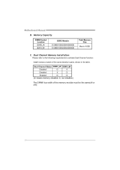
...http://www.adobe.com /produ cts/a crobat /reads tep2 .html 18 Please download the latest version of Acrobat Reader software from the paperback manual, we also provide manual in the Driver DVD. Driver Installation To install the driver, please click on the Software icon. Note: If this window didn't show...you installed your operating system, please insert the Fully Setup Driver DVD into your system, click on each device driver to browse for available manual. You will see the following window after you insert the Driver DVD, please use file browser to locate and execute the file SETUP.EXE...
...http://www.adobe.com /produ cts/a crobat /reads tep2 .html 18 Please download the latest version of Acrobat Reader software from the paperback manual, we also provide manual in the Driver DVD. Driver Installation To install the driver, please click on the Software icon. Note: If this window didn't show...you installed your operating system, please insert the Fully Setup Driver DVD into your system, click on each device driver to browse for available manual. You will see the following window after you insert the Driver DVD, please use file browser to locate and execute the file SETUP.EXE...
Setup Manual
Page 22
Motherboard Manual After filling up this information to the following web http://www.biostar.com.tw/app/en-us/about/contact.php for your confirmation; A warning dialog would appear asking for getting our contact information. 20 click "Send" to ...
Motherboard Manual After filling up this information to the following web http://www.biostar.com.tw/app/en-us/about/contact.php for your confirmation; A warning dialog would appear asking for getting our contact information. 20 click "Send" to ...

Setup Manual
Page 24
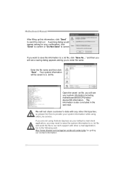
... take minutes. All the information and content above are subject to be updated. The actual information and settings on Open. Motherboard Manual Before doing this process may be slightly different from the website. After the BIOS Backup procedure, the open any other applications during this... manual. 22 Click Update BIOS button, a dialog will update BIOS with the proper BIOS file, and this , please download the proper BIOS file...
... take minutes. All the information and content above are subject to be updated. The actual information and settings on Open. Motherboard Manual Before doing this process may be slightly different from the website. After the BIOS Backup procedure, the open any other applications during this... manual. 22 Click Update BIOS button, a dialog will update BIOS with the proper BIOS file, and this , please download the proper BIOS file...
Setup Manual
Page 26
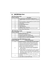
... cards is an integrated part of the system board, the board may be faulty. 24 Fatal error indicating a serious problem with known good modules. Motherboard Manual 4.4 AMI BIOS BEEP CODE Boot Block Beep Codes Number of Beeps Description 1 No media present. (Insert diskette in floppy drive A:) 2 "AMIBOOT.ROM" file not found...
... cards is an integrated part of the system board, the board may be faulty. 24 Fatal error indicating a serious problem with known good modules. Motherboard Manual 4.4 AMI BIOS BEEP CODE Boot Block Beep Codes Number of Beeps Description 1 No media present. (Insert diskette in floppy drive A:) 2 "AMIBOOT.ROM" file not found...

Setup Manual
Page 28
Motherboard Manual This page is intentionally left blank. 26
Motherboard Manual This page is intentionally left blank. 26

Bios Setup
Page 1
H61MGB/H61MLB/H61MHB UEFI BIOS Manual UEFI BIOS Setup 1 1 Main Menu 3 2 Advanced Menu 4 3 Chipset Menu 17 4 Boot Menu 22 5 Security Menu 24 6 Performance Menu 25 7 Exit Menu 31 i
H61MGB/H61MLB/H61MHB UEFI BIOS Manual UEFI BIOS Setup 1 1 Main Menu 3 2 Advanced Menu 4 3 Chipset Menu 17 4 Boot Menu 22 5 Security Menu 24 6 Performance Menu 25 7 Exit Menu 31 i
Bios Setup
Page 2
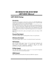
... It provides ASL code for power management and device configuration capabilities as defined in the AMI UEFI BIOS Setup program on this manual will to NVRAM. The Setup program allows users to modify the basic system configuration and save these settings to guide you through...BIOS support Version 1.0/2.0 of the booting process, loading and executing the operating system. H61MGB/H61MLB/H61MHB UEFI BIOS Manual UEFI BIOS Setup Introduction The purpose of this manual is supported. 1 BIOS activates at the first stage of Advanced Configuration and Power interface specification (ACPI). Plug ...
... It provides ASL code for power management and device configuration capabilities as defined in the AMI UEFI BIOS Setup program on this manual will to NVRAM. The Setup program allows users to modify the basic system configuration and save these settings to guide you through...BIOS support Version 1.0/2.0 of the booting process, loading and executing the operating system. H61MGB/H61MLB/H61MHB UEFI BIOS Manual UEFI BIOS Setup Introduction The purpose of this manual is supported. 1 BIOS activates at the first stage of Advanced Configuration and Power interface specification (ACPI). Plug ...

Bios Setup
Page 3
...for most conditions to ensure system's compatibility and stability. Use Load Setup Default under the Exit Menu. The UEFI BIOS information described in this manual is subject to be changed without notice. Using Setup When starting up the computer, press during the Power-On Self-Test (POST) to ...Help description at the bottom right corner, and you can use these keys to enter the UEFI BIOS setup utility. H61MGB/H61MLB/H61MHB UEFI BIOS Manual Supported CPUs This AMI UEFI BIOS supports the Intel CPU. z For better system performance, the UEFI BIOS firmware is providing a brief description of...
...for most conditions to ensure system's compatibility and stability. Use Load Setup Default under the Exit Menu. The UEFI BIOS information described in this manual is subject to be changed without notice. Using Setup When starting up the computer, press during the Power-On Self-Test (POST) to ...Help description at the bottom right corner, and you can use these keys to enter the UEFI BIOS setup utility. H61MGB/H61MLB/H61MHB UEFI BIOS Manual Supported CPUs This AMI UEFI BIOS supports the Intel CPU. z For better system performance, the UEFI BIOS firmware is providing a brief description of...

Bios Setup
Page 4
... Opt. Copyright© 201x, American Megatrends, Inc. System Date Set the system date. System Time Set the system internal clock. H61MGB/H61MLB/H61MHB UEFI BIOS Manual 1 Main Menu Once you set the date. Note that the 'Day' automatically changes when you enter AMI UEFI BIOS Setup Utility, the Main Menu will...
... Opt. Copyright© 201x, American Megatrends, Inc. System Date Set the system date. System Time Set the system internal clock. H61MGB/H61MLB/H61MHB UEFI BIOS Manual 1 Main Menu Once you set the date. Note that the 'Day' automatically changes when you enter AMI UEFI BIOS Setup Utility, the Main Menu will...
Bios Setup
Page 5
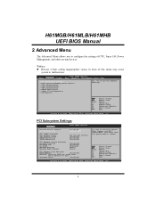
..., and other system devices. General Help Optimized Defaults Save & Reset Exit Version x.xx.xxxx. Copyright© 201x, American Megatrends, Inc. 4 H61MGB/H61MLB/H61MHB UEFI BIOS Manual 2 Advanced Menu The Advanced Menu allows you to configure the settings of multiple Opiton ROMs (Legacy and EFI Compatible), specifies what PCI Option ROM to...
..., and other system devices. General Help Optimized Defaults Save & Reset Exit Version x.xx.xxxx. Copyright© 201x, American Megatrends, Inc. 4 H61MGB/H61MLB/H61MHB UEFI BIOS Manual 2 Advanced Menu The Advanced Menu allows you to configure the settings of multiple Opiton ROMs (Legacy and EFI Compatible), specifies what PCI Option ROM to...

