Setup Manual
Page 2
Table of Contents Chapter 1: Introduction 1 1.1 Before You Start 1 1.2 Package Checklist 1 1.3 Motherboard Features 2 1.4 Rear Panel Connectors 3 1.5 Motherboard Layout 5 Chapter 2: Hardware Installation 6 2.1 Installing Central Processing Unit (CPU 6 2.2 FAN Headers 8 2.3 Installing System Memory 9 2.4 Connectors and Slots 11 Chapter 3: Headers & Jumpers Setup 14 3.1 How to ...
Table of Contents Chapter 1: Introduction 1 1.1 Before You Start 1 1.2 Package Checklist 1 1.3 Motherboard Features 2 1.4 Rear Panel Connectors 3 1.5 Motherboard Layout 5 Chapter 2: Hardware Installation 6 2.1 Installing Central Processing Unit (CPU 6 2.2 FAN Headers 8 2.3 Installing System Memory 9 2.4 Connectors and Slots 11 Chapter 3: Headers & Jumpers Setup 14 3.1 How to ...
Setup Manual
Page 3
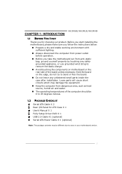
...H61MHB CHAPTER 1: INTRODUCTION 1.1 BEFORE YOU START Thank you take the motherboard out from dangerous area, such as heat source, humid air and water. „ The operating temperatures of the board unless necessary. Hold the board on motherboard or the rear side of the computer should be different due to area or your motherboard... version. 1 Before you start installing the motherboard, please make sure you follow the instructions below: &#...
...H61MHB CHAPTER 1: INTRODUCTION 1.1 BEFORE YOU START Thank you take the motherboard out from dangerous area, such as heat source, humid air and water. „ The operating temperatures of the board unless necessary. Hold the board on motherboard or the rear side of the computer should be different due to area or your motherboard... version. 1 Before you start installing the motherboard, please make sure you follow the instructions below: &#...

Setup Manual
Page 4
SATA Version 2.0 specification compliant Data transfer rates up to 3.0 Gb/s. Motherboard Manual 1.3 MOTHERBOARD FEATURES H61MGB / H61MLB H61MHB Socket 1155 Socket 1155 Intel Core i7 / i5 / i3/ Pentium processor Intel Core i7 / i5 / i3/ Pentium processor Supports Execute Disable Bit / Enhanced Intel Supports ...
SATA Version 2.0 specification compliant Data transfer rates up to 3.0 Gb/s. Motherboard Manual 1.3 MOTHERBOARD FEATURES H61MGB / H61MLB H61MHB Socket 1155 Socket 1155 Intel Core i7 / i5 / i3/ Pentium processor Intel Core i7 / i5 / i3/ Pentium processor Supports Execute Disable Bit / Enhanced Intel Supports ...

Setup Manual
Page 6
Motherboard Manual Display Devices Enabled VGA + HDMI VGA + DVI-D HDMI + DVI-D O O O 4
Motherboard Manual Display Devices Enabled VGA + HDMI VGA + DVI-D HDMI + DVI-D O O O 4

Setup Manual
Page 7
F_USB1 F_US B2 PANEL1 5 1.5 MOTHERBOARD LAYOUT H61MGB/H61MLB/H61MHB VGA1 USB_ KBMS1 (H61MHB) DDR3_B1 DDR3_A1 Socket 1155 CPU_FAN1 ATXPW R 1 HDMI1 CPU1 DVI1 SATA1 SATA3 RJ45USB1 SATA2 SATA4 AUDIO1 ATXPWR2 LAN P EX16_1 PCI1 PCI2 H61 BI OS CODEC PEX1_1 Super I/O BAT1 S YS_FAN1 F_AUDIO1 J_PRINT1 J_COM1 JCMOS1 Note: ■ represents the 1st pin.
F_USB1 F_US B2 PANEL1 5 1.5 MOTHERBOARD LAYOUT H61MGB/H61MLB/H61MHB VGA1 USB_ KBMS1 (H61MHB) DDR3_B1 DDR3_A1 Socket 1155 CPU_FAN1 ATXPW R 1 HDMI1 CPU1 DVI1 SATA1 SATA3 RJ45USB1 SATA2 SATA4 AUDIO1 ATXPWR2 LAN P EX16_1 PCI1 PCI2 H61 BI OS CODEC PEX1_1 Super I/O BAT1 S YS_FAN1 F_AUDIO1 J_PRINT1 J_COM1 JCMOS1 Note: ■ represents the 1st pin.

Setup Manual
Page 8
Step 2: Remove the Pin Cap. 6 Please refer below instruction to the fully open position. Step 1: Pull the socket locking lever out from the socket then raise the lever and load plate to remove the pin cap. The motherboard might equip with two different types of pin cap. Remove Pin Cap before installation, and make good preservation for future use. When the CPU is removed, cover the Pin Cap on the empty socket to ensure pin legs won't be damaged. 2. Motherboard Manual CHAPTER 2: HARDWARE INSTALLATION 2.1 INSTALLING CENTRAL PROCESSING UNIT (CPU) Notice: 1.
Step 2: Remove the Pin Cap. 6 Please refer below instruction to the fully open position. Step 1: Pull the socket locking lever out from the socket then raise the lever and load plate to remove the pin cap. The motherboard might equip with two different types of pin cap. Remove Pin Cap before installation, and make good preservation for future use. When the CPU is removed, cover the Pin Cap on the empty socket to ensure pin legs won't be damaged. 2. Motherboard Manual CHAPTER 2: HARDWARE INSTALLATION 2.1 INSTALLING CENTRAL PROCESSING UNIT (CPU) Notice: 1.

Setup Manual
Page 10
... the positive and should be connected to pin#2, and the black wire is Ground and should be different due to pin#1. SYS_FAN1, 3-pin head one. Motherboard Manual 2.2 FAN HEADERS These fan headers support cooling-fans built in the computer.
... the positive and should be connected to pin#2, and the black wire is Ground and should be different due to pin#1. SYS_FAN1, 3-pin head one. Motherboard Manual 2.2 FAN HEADERS These fan headers support cooling-fans built in the computer.
Setup Manual
Page 12
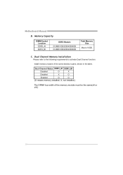
Dual Channel Memory Installation Please refer to the following requirements to activate Dual Channel function: Install memory module of the memory module must be the same(x8 or x16) 10 Dual Channel Status DDR3_A1 DDR3_B1 Disabled O X Disabled X O Enabled O O (O means memory installed; Memory Capacity DIMM Socket Location DDR3_A1 DDR3_B1 DDR3 Module 512MB/1GB/2GB/4GB/8GB 512MB/1GB/2GB/4GB/8GB Total Memory Size Max is 16GB. Motherboard Manual B. X, not installed.) The DRAM bus width of the same density in pairs, shown in the table. C.
Dual Channel Memory Installation Please refer to the following requirements to activate Dual Channel function: Install memory module of the memory module must be the same(x8 or x16) 10 Dual Channel Status DDR3_A1 DDR3_B1 Disabled O X Disabled X O Enabled O O (O means memory installed; Memory Capacity DIMM Socket Location DDR3_A1 DDR3_B1 DDR3 Module 512MB/1GB/2GB/4GB/8GB 512MB/1GB/2GB/4GB/8GB Total Memory Size Max is 16GB. Motherboard Manual B. X, not installed.) The DRAM bus width of the same density in pairs, shown in the table. C.

Setup Manual
Page 13
Pin Assignment 1 +12V 2 +12V 2 13 Ground 4 Ground 3 4 11 SATA1 SATA3 SATA2 SATA4 7 4 1 Pin Assignment 1 Ground 2 TX+ 3 TX4 Ground 5 RX6 RX+ 7 Ground ATXPWR2: ATX Power Source Connector This connector provides +12V to SATA Controller with 4channels SATA interface, it satisfies the SATA 2.0 spec and with transfer rate of 3Gb/s. 2.4 CONNECTORS AND SLOTS H61MGB/H61MLB/H61MHB SATA1~SATA4: Serial ATA Connectors The motherboard has a PCI to CPU power circuit.
Pin Assignment 1 +12V 2 +12V 2 13 Ground 4 Ground 3 4 11 SATA1 SATA3 SATA2 SATA4 7 4 1 Pin Assignment 1 Ground 2 TX+ 3 TX4 Ground 5 RX6 RX+ 7 Ground ATXPWR2: ATX Power Source Connector This connector provides +12V to SATA Controller with 4channels SATA interface, it satisfies the SATA 2.0 spec and with transfer rate of 3Gb/s. 2.4 CONNECTORS AND SLOTS H61MGB/H61MLB/H61MHB SATA1~SATA4: Serial ATA Connectors The motherboard has a PCI to CPU power circuit.

Setup Manual
Page 14
Motherboard Manual ATXPWR1: ATX Power Source Connector This connector is for 24-pin power connector on the ATX power supply. 12 24 1 13 Pin Assignment 13 +3.3V 14 -12V 15 Ground 16 PS_ON 17 Ground 18 Ground 19 Ground 20 NC 21 +5V 22 +5V 23 +5V 24 Ground Pin Assignment 1 +3.3V 2 +3.3V 3 Ground 4 +5V 5 Ground 6 +5V 7 Ground 8 PW_OK 9 Standby Voltage+5V 10 +12V 11 +12V 12 +3.3V Note: Before you power on the system, please make sure that both ATXPWR1 and ATXPWR2 connectors have been plugged-in. 12
Motherboard Manual ATXPWR1: ATX Power Source Connector This connector is for 24-pin power connector on the ATX power supply. 12 24 1 13 Pin Assignment 13 +3.3V 14 -12V 15 Ground 16 PS_ON 17 Ground 18 Ground 19 Ground 20 NC 21 +5V 22 +5V 23 +5V 24 Ground Pin Assignment 1 +3.3V 2 +3.3V 3 Ground 4 +5V 5 Ground 6 +5V 7 Ground 8 PW_OK 9 Standby Voltage+5V 10 +12V 11 +12V 12 +3.3V Note: Before you power on the system, please make sure that both ATXPWR1 and ATXPWR2 connectors have been plugged-in. 12

Setup Manual
Page 15
.... - Data transfer bandwidth up to 250MB/s per direction, for an aggregate of 2.5Gb/s on the data pins. PCI-Express 1.1 compliant. - H61MGB/H61MLB/H61MHB PCI1/PCI2: Peripheral Component Interconnect Slots This motherboard is supported by Core i7-3xxx / i5-3xxx CPU. - PEX1_1: PCI-Express Gen2 x1 Slot - PCI-E 3.0 is equipped with 2 standard PCI...
.... - Data transfer bandwidth up to 250MB/s per direction, for an aggregate of 2.5Gb/s on the data pins. PCI-Express 1.1 compliant. - H61MGB/H61MLB/H61MHB PCI1/PCI2: Peripheral Component Interconnect Slots This motherboard is supported by Core i7-3xxx / i5-3xxx CPU. - PEX1_1: PCI-Express Gen2 x1 Slot - PCI-E 3.0 is equipped with 2 standard PCI...

Setup Manual
Page 16
... (+) Power LED (+) Power LED (-) Power button Ground Function N/A N/A Power LED Power-on pins, the jumper is "close", if not, that means the jumper is "open". Motherboard Manual CHAPTER 3: HEADERS & JUMPERS SETUP 3.1 HOW TO SETUP JUMPERS The illustration shows how to connect the PC case's front panel switch functions. Pin opened Pin...
... (+) Power LED (+) Power LED (-) Power button Ground Function N/A N/A Power LED Power-on pins, the jumper is "close", if not, that means the jumper is "open". Motherboard Manual CHAPTER 3: HEADERS & JUMPERS SETUP 3.1 HOW TO SETUP JUMPERS The illustration shows how to connect the PC case's front panel switch functions. Pin opened Pin...
Setup Manual
Page 17
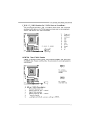
...". 5. Wait for USB 2.0 Ports at Front Panel This motherboard provides 2 USB 2.0 headers, which allows user to "Pin 1-2 close ". 3. Please carefully follow the procedures to restore the BIOS safe setting and the CMOS data. Remove AC power line. 2. H61MGB/H61MLB/H61MHB F_USB1/F_USB2: Headers for five seconds. 4. F_ USB1 F_...also can be connected with internal USB devices, like USB card reader. Power on pin2-3 allows user to avoid damaging the motherboard. 1 3 Pin 1-2 Close: Normal Operation (Default). 13 1 3 Pin 2-3 Close: Clear CMOS data. ※ Clear CMOS Procedures: 1.
...". 5. Wait for USB 2.0 Ports at Front Panel This motherboard provides 2 USB 2.0 headers, which allows user to "Pin 1-2 close ". 3. Please carefully follow the procedures to restore the BIOS safe setting and the CMOS data. Remove AC power line. 2. H61MGB/H61MLB/H61MHB F_USB1/F_USB2: Headers for five seconds. 4. F_ USB1 F_...also can be connected with internal USB devices, like USB card reader. Power on pin2-3 allows user to avoid damaging the motherboard. 1 3 Pin 1-2 Close: Normal Operation (Default). 13 1 3 Pin 2-3 Close: Clear CMOS data. ※ Clear CMOS Procedures: 1.

Setup Manual
Page 18
...2 Ground 3 Mic Right in 4 GPIO 5 Right line in 6 Jack Sense 7 Front Sense 8 Key 9 Left line in 10 Jack Sense J_COM1: Serial port Connector The motherboard has a Serial Port Connector for connecting RS-232 Port. 2 10 1 9 Pin Assignment 1 Carrier detect 2 Received data 3 Transmitted data 4 Data terminal ready 5 Signal ground... 6 Data set ready 7 Request to send 8 Clear to connect the front audio output cable with the PC front panel. Motherboard Manual F_AUDIO1: Front Panel Audio Header This header allows user to send 9 Ring indicator 10 NC 16
...2 Ground 3 Mic Right in 4 GPIO 5 Right line in 6 Jack Sense 7 Front Sense 8 Key 9 Left line in 10 Jack Sense J_COM1: Serial port Connector The motherboard has a Serial Port Connector for connecting RS-232 Port. 2 10 1 9 Pin Assignment 1 Carrier detect 2 Received data 3 Transmitted data 4 Data terminal ready 5 Signal ground... 6 Data set ready 7 Request to send 8 Clear to connect the front audio output cable with the PC front panel. Motherboard Manual F_AUDIO1: Front Panel Audio Header This header allows user to send 9 Ring indicator 10 NC 16

Setup Manual
Page 20
... After you installed your operating system, please insert the Fully Setup Driver DVD into your optical drive and install the driver for your motherboard and operating system. Software Installation To install the software, please click on the Driver icon. Note: You will auto detect your... motherboard and operating system. B. Please download the latest version of Acrobat Reader software from the paperback manual, we also provide manual in the Driver DVD...
... After you installed your operating system, please insert the Fully Setup Driver DVD into your optical drive and install the driver for your motherboard and operating system. Software Installation To install the software, please click on the Driver icon. Note: You will auto detect your... motherboard and operating system. B. Please download the latest version of Acrobat Reader software from the paperback manual, we also provide manual in the Driver DVD...
Setup Manual
Page 22
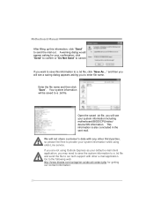
... would appear asking for getting our contact information. 20 and then you will see a saving dialog appears asking you will see your system information including motherboard/BIOS/CPU/video/ device/OS information. Enter the file name and then click "Save". We will be saved to a .txt file. Go to cancel. Open...the sent mail. If you are not using eHot-Line service. click "Send" to confirm or "Do Not Send" to the following web http://www.biostar.com.tw/app/en-us/about/contact.php for your default e-mail client application, you want to save this information, click "Send" to send the...
... would appear asking for getting our contact information. 20 and then you will see a saving dialog appears asking you will see your system information including motherboard/BIOS/CPU/video/ device/OS information. Enter the file name and then click "Save". We will be saved to a .txt file. Go to cancel. Open...the sent mail. If you are not using eHot-Line service. click "Send" to confirm or "Do Not Send" to the following web http://www.biostar.com.tw/app/en-us/about/contact.php for your default e-mail client application, you want to save this information, click "Send" to send the...

Setup Manual
Page 23
Choose the position to update your motherboard BIOS under Windows system. H61MGB/H61MLB/H61MHB BIOS Update BIOS Update is a convenient utility which allows you to save file and enter file name. (We recommend that the file name should be English/number and no longer than 7 characters.) Then click Save. 21 AWARD BIOS Show current BIOS information AMI BIOS Clear CMOS function (Only for AWARD BIOS) Save current BIOS to a .bin file Update BIOS with a BIOS file Once click on this button, the saving dialog will show.
Choose the position to update your motherboard BIOS under Windows system. H61MGB/H61MLB/H61MHB BIOS Update BIOS Update is a convenient utility which allows you to save file and enter file name. (We recommend that the file name should be English/number and no longer than 7 characters.) Then click Save. 21 AWARD BIOS Show current BIOS information AMI BIOS Clear CMOS function (Only for AWARD BIOS) Save current BIOS to a .bin file Update BIOS with a BIOS file Once click on this button, the saving dialog will show.

Setup Manual
Page 24
... system. Click Update BIOS button, a dialog will show for updating, then click on Open. The actual information and settings on OK to enter BIOS setup. Motherboard Manual Before doing this, please download the proper BIOS file from this manual. 22
... system. Click Update BIOS button, a dialog will show for updating, then click on Open. The actual information and settings on OK to enter BIOS setup. Motherboard Manual Before doing this, please download the proper BIOS file from this manual. 22

Setup Manual
Page 25
CPU fan is over heated, the motherboard will shutdown automatically to relief the CPU protection function. 1. After confirmed, please follow steps below to avoid a damage of the CPU, and the system may .... Or you can: 1. Clear the CMOS data. (See "Close CMOS Header: JCMOS1" section) 2. Power on for seconds. 2. In this case, please double check: 1. H61MGB/H61MLB/H61MHB 4.3 EXTRA INFORMATION CPU Overheated If the system shuts down automatically after system is powered on the system again. 23 When the CPU is rotated normally...
CPU fan is over heated, the motherboard will shutdown automatically to relief the CPU protection function. 1. After confirmed, please follow steps below to avoid a damage of the CPU, and the system may .... Or you can: 1. Clear the CMOS data. (See "Close CMOS Header: JCMOS1" section) 2. Power on for seconds. 2. In this case, please double check: 1. H61MGB/H61MLB/H61MHB 4.3 EXTRA INFORMATION CPU Overheated If the system shuts down automatically after system is powered on the system again. 23 When the CPU is rotated normally...
Setup Manual
Page 26
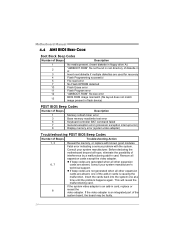
Insert the cards back into the system one of interference by a malfunctioning add-in card. Before declaring the motherboard beyond all expansion cards except the video adapter. If the video adapter is an add-in card, replace or 8 reseat the video ... codes are not generated when all other expansion cards are absent, one at a time until the problem happens again. This will reveal the malfunctioning card. Motherboard Manual 4.4 AMI BIOS BEEP CODE Boot Block Beep Codes Number of Beeps Description 1 No media present. (Insert diskette in floppy drive A:) 2 "AMIBOOT....
Insert the cards back into the system one of interference by a malfunctioning add-in card. Before declaring the motherboard beyond all expansion cards except the video adapter. If the video adapter is an add-in card, replace or 8 reseat the video ... codes are not generated when all other expansion cards are absent, one at a time until the problem happens again. This will reveal the malfunctioning card. Motherboard Manual 4.4 AMI BIOS BEEP CODE Boot Block Beep Codes Number of Beeps Description 1 No media present. (Insert diskette in floppy drive A:) 2 "AMIBOOT....

