
Setup Manual
Page 2
Table of Contents Chapter 1: Introduction 1 1.1 Before You Start 1 1.2 Package Checklist 1 1.3 Motherboard Features 2 1.4 Rear Panel Connectors 3 1.5 Motherboard Layout 4 Chapter 2: Hardware Installation 5 2.1 Installing Central Processing Unit (CPU 5 2.2 FAN Headers 7 2.3 Installing System Memory 8 2.4 Connectors and Slots 10 Chapter 3: Headers & Jumpers Setup 13 3.1 How to ...
Table of Contents Chapter 1: Introduction 1 1.1 Before You Start 1 1.2 Package Checklist 1 1.3 Motherboard Features 2 1.4 Rear Panel Connectors 3 1.5 Motherboard Layout 4 Chapter 2: Hardware Installation 5 2.1 Installing Central Processing Unit (CPU 5 2.2 FAN Headers 7 2.3 Installing System Memory 8 2.4 Connectors and Slots 10 Chapter 3: Headers & Jumpers Setup 13 3.1 How to ...

Setup Manual
Page 3
... try to remove the static charge. „ Avoid touching the components on motherboard or the rear side of the board unless necessary. CHAPTER 1: INTRODUCTION A780L3B 1.1 BEFORE YOU START Thank you take the motherboard out from dangerous area, such as heat source, humid air and water. ...1.2 PACKAGE CHECKLIST Serial ATA Cable X 2 Rear I/O Panel for choosing our product. Before you start installing the motherboard, please make sure ...
... try to remove the static charge. „ Avoid touching the components on motherboard or the rear side of the board unless necessary. CHAPTER 1: INTRODUCTION A780L3B 1.1 BEFORE YOU START Thank you take the motherboard out from dangerous area, such as heat source, humid air and water. ...1.2 PACKAGE CHECKLIST Serial ATA Cable X 2 Rear I/O Panel for choosing our product. Before you start installing the motherboard, please make sure ...

Setup Manual
Page 4
Motherboard Manual 1.3 MOTHERBOARD FEATURES SPEC Socket AM3 AMD 64 Architecture enables 32 and 64 bit CPU AMD Sempron / Phenom II / Athlon II computing processors (Maximum Watt: 95W) Supports ...
Motherboard Manual 1.3 MOTHERBOARD FEATURES SPEC Socket AM3 AMD 64 Architecture enables 32 and 64 bit CPU AMD Sempron / Phenom II / Athlon II computing processors (Maximum Watt: 95W) Supports ...

Setup Manual
Page 6
SATA4 SATA3 4 Motherboard Manual 1.5 MOTHERBOARD LAYOUT KBMS1 C PU _FA N1 ATX PW R2 ATX PW R1 DDR3_ A 1 D DR 3_ B1 BIOS Socket AM3 VGA1 U SB 1 R J45US B 1 A UD I O1 F_AU DI O1 LAN C odec AMD 760G PEX16_1 Super I/O BAT PCI1 J_PRINT1 SYS_FAN1 F_U S B1 F_USB2 AMD SB700/ SB710 SATA1 SATA2 PANEL1 J C MOS1 Note: ■ represents the 1st pin.
SATA4 SATA3 4 Motherboard Manual 1.5 MOTHERBOARD LAYOUT KBMS1 C PU _FA N1 ATX PW R2 ATX PW R1 DDR3_ A 1 D DR 3_ B1 BIOS Socket AM3 VGA1 U SB 1 R J45US B 1 A UD I O1 F_AU DI O1 LAN C odec AMD 760G PEX16_1 Super I/O BAT PCI1 J_PRINT1 SYS_FAN1 F_U S B1 F_USB2 AMD SB700/ SB710 SATA1 SATA2 PANEL1 J C MOS1 Note: ■ represents the 1st pin.

Setup Manual
Page 8
This completes the installation. 6 Motherboard Manual Step 3: Hold the CPU down firmly, and then close the lever toward direct B to the CPU_FAN1. Step 4: Put the CPU Fan on the CPU and buckle it. Connect the CPU FAN power cable to complete the installation.
This completes the installation. 6 Motherboard Manual Step 3: Hold the CPU down firmly, and then close the lever toward direct B to the CPU_FAN1. Step 4: Put the CPU Fan on the CPU and buckle it. Connect the CPU FAN power cable to complete the installation.

Setup Manual
Page 10
Align a DIMM on the slot such that the notch on the DIMM matches the break on the Slot. 2. DDR 3_ A1 DDR 3_ B1 Motherboard Manual 2.3 INSTALLING SYSTEM MEMORY A. Unlock a DIMM slot by pressing the retaining clips outward. Memory Modules 1. Insert the DIMM vertically and firmly into the slot until the retaining chip snap back in place and the DIMM is properly seated. 8
Align a DIMM on the slot such that the notch on the DIMM matches the break on the Slot. 2. DDR 3_ A1 DDR 3_ B1 Motherboard Manual 2.3 INSTALLING SYSTEM MEMORY A. Unlock a DIMM slot by pressing the retaining clips outward. Memory Modules 1. Insert the DIMM vertically and firmly into the slot until the retaining chip snap back in place and the DIMM is properly seated. 8

Setup Manual
Page 12
Motherboard Manual 2.4 CONNECTORS AND SLOTS SATA1~SATA4: Serial ATA Connectors The motherboard has a PCI to CPU power circuit. 32 41 Pin Assignment 1 +12V 2 +12V 3 Ground 4 Ground 10 Pin Assignment 1 Ground 2 TX+ 3 TX- 4 Ground SATA4 SATA3 5 RX6 RX+ 7 Ground SATA1 SATA2 14 7 ATXPWR2: ATX Power Source Connector This connector provides +12V to SATA Controller with 4channels SATA interface, it satisfies the SATA 2.0 spec and with transfer rate of 3Gb/s.
Motherboard Manual 2.4 CONNECTORS AND SLOTS SATA1~SATA4: Serial ATA Connectors The motherboard has a PCI to CPU power circuit. 32 41 Pin Assignment 1 +12V 2 +12V 3 Ground 4 Ground 10 Pin Assignment 1 Ground 2 TX+ 3 TX- 4 Ground SATA4 SATA3 5 RX6 RX+ 7 Ground SATA1 SATA2 14 7 ATXPWR2: ATX Power Source Connector This connector provides +12V to SATA Controller with 4channels SATA interface, it satisfies the SATA 2.0 spec and with transfer rate of 3Gb/s.

Setup Manual
Page 14
PCI-Express supports a raw bit-rate of 8GB/s totally. - PEX16_1 PCI1: Peripheral Component Interconnect Slot This motherboard is a bus standard for expansion cards. PCI1 12 Motherboard Manual PEX16_1: PCI-Express X16 Slot - PCI-Express 2.0 compliant. - Maximum theoretical realized bandwidth of 4GB/s simultaneously per direction, for Peripheral Component Interconnect, and it is equipped with 1 standard PCI slot. PCI stands for an aggregate of 2.5Gb/s on the data pins. This PCI slot is designated as 32 bits.
PCI-Express supports a raw bit-rate of 8GB/s totally. - PEX16_1 PCI1: Peripheral Component Interconnect Slot This motherboard is a bus standard for expansion cards. PCI1 12 Motherboard Manual PEX16_1: PCI-Express X16 Slot - PCI-Express 2.0 compliant. - Maximum theoretical realized bandwidth of 4GB/s simultaneously per direction, for Peripheral Component Interconnect, and it is equipped with 1 standard PCI slot. PCI stands for an aggregate of 2.5Gb/s on the data pins. This PCI slot is designated as 32 bits.
Setup Manual
Page 16
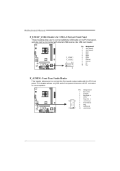
... Assignment 1 Mic Left in 2 Ground 3 Mic Right in 4 GPIO 5 Right line in 10 9 6 Jack Sense 7 Front Sense 8 Key 9 Left line in 2 1 10 Jack Sense 14 Motherboard Manual F_USB1/F_USB2: Headers for USB 2.0 Ports at Front Panel These headers allow user to connect the front audio output cable with internal USB devices...
... Assignment 1 Mic Left in 2 Ground 3 Mic Right in 4 GPIO 5 Right line in 10 9 6 Jack Sense 7 Front Sense 8 Key 9 Left line in 2 1 10 Jack Sense 14 Motherboard Manual F_USB1/F_USB2: Headers for USB 2.0 Ports at Front Panel These headers allow user to connect the front audio output cable with internal USB devices...

Setup Manual
Page 18
Power on pin2-3 allows user to "Pin 2-3 close ". 5. Pease carefully follow the procedures to "Pin 1-2 close ". 3. Set the jumper to restore BIOS safe setting and CMOS data. Remove AC power line. 2. Set the jumper to avoid damaging the motherboard. 13 Pin 1-2 Close: Normal Operation (default). 13 13 Pin 2-3 Close: Clear CMOS data. ※ Clear CMOS Procedures: 1. Motherboard Manual JCMOS1: Clear CMOS Jumper Placing the jumper on the AC. 6. Load Optimal Defaults and save settings in CMOS. 16 Wait for five seconds. 4.
Power on pin2-3 allows user to "Pin 2-3 close ". 5. Pease carefully follow the procedures to "Pin 1-2 close ". 3. Set the jumper to restore BIOS safe setting and CMOS data. Remove AC power line. 2. Set the jumper to avoid damaging the motherboard. 13 Pin 1-2 Close: Normal Operation (default). 13 13 Pin 2-3 Close: Clear CMOS data. ※ Clear CMOS Procedures: 1. Motherboard Manual JCMOS1: Clear CMOS Jumper Placing the jumper on the AC. 6. Load Optimal Defaults and save settings in CMOS. 16 Wait for five seconds. 4.

Setup Manual
Page 20
... on a second redundant drive in a RAID 1 array system. Drawbacks: Requires 2 drives for small databases or any other drive. - Block 1 Block 2 Block 3 Block 1 Block 2 Block 3 18 Motherboard Manual RAID 1: Every read and write is corrupted or becomes unavailable because of a hardware failure. Features and Benefits - Uses: RAID 1 is ideal for the storage...
... on a second redundant drive in a RAID 1 array system. Drawbacks: Requires 2 drives for small databases or any other drive. - Block 1 Block 2 Block 3 Block 1 Block 2 Block 3 18 Motherboard Manual RAID 1: Every read and write is corrupted or becomes unavailable because of a hardware failure. Features and Benefits - Uses: RAID 1 is ideal for the storage...

Setup Manual
Page 22
... the installation program. Software Installation To install the software, please click on the Driver icon. C. Note: You will auto detect your motherboard and operating system. B. Please download the latest version of Acrobat Reader software from the paperback manual, we also provide manual in the ...you insert the CD The setup guide will need Acrobat Reader to locate and execute the file SETUP.EXE under your optical drive. Motherboard Manual CHAPTER 5: USEFUL HELP 5.1 DRIVER INSTALLATION NOTE After you installed your operating system, please insert the Fully Setup Driver CD ...
... the installation program. Software Installation To install the software, please click on the Driver icon. C. Note: You will auto detect your motherboard and operating system. B. Please download the latest version of Acrobat Reader software from the paperback manual, we also provide manual in the ...you insert the CD The setup guide will need Acrobat Reader to locate and execute the file SETUP.EXE under your optical drive. Motherboard Manual CHAPTER 5: USEFUL HELP 5.1 DRIVER INSTALLATION NOTE After you installed your operating system, please insert the Fully Setup Driver CD ...

Setup Manual
Page 24
Motherboard Manual After filling up this information to a .txt file, click "Save As..." A warning dialog would appear asking for getting our contact information. 22 and then ..., click "Send" to our tech support with any other e-mail application. click "Send" to confirm or "Do Not Send" to the following web http://www.biostar.com.tw/app/en-us/about/contact.php for your system information including motherboard/BIOS/CPU/video/ device/OS information.
Motherboard Manual After filling up this information to a .txt file, click "Save As..." A warning dialog would appear asking for getting our contact information. 22 and then ..., click "Send" to our tech support with any other e-mail application. click "Send" to confirm or "Do Not Send" to the following web http://www.biostar.com.tw/app/en-us/about/contact.php for your system information including motherboard/BIOS/CPU/video/ device/OS information.

Setup Manual
Page 25
Show current BIOS information Update BIOS from the Internet Update BIOS with a BIOS file Once click on this button, the saving dialog will show. Save current BIOS to update your motherboard BIOS under Windows system. A780L3B BIOS Update BIOS Update is a convenient utility which allows you to a .bin file 23 Choose the position to save file and enter file name. (We recommend that the file name should be English/number and no longer than 7 characters.) Then click Save.
Show current BIOS information Update BIOS from the Internet Update BIOS with a BIOS file Once click on this button, the saving dialog will show. Save current BIOS to update your motherboard BIOS under Windows system. A780L3B BIOS Update BIOS Update is a convenient utility which allows you to a .bin file 23 Choose the position to save file and enter file name. (We recommend that the file name should be English/number and no longer than 7 characters.) Then click Save.

Setup Manual
Page 26
... may be changed without notice. Please choose the proper BIOS file for BIOS backup and refer to be updated. BIOS Update is being continuously updated. Motherboard Manual Before doing this process. All the information and content above are subject to restart the system. Click Yes for updating, then click on OK...
... may be changed without notice. Please choose the proper BIOS file for BIOS backup and refer to be updated. BIOS Update is being continuously updated. Motherboard Manual Before doing this process. All the information and content above are subject to restart the system. Click Yes for updating, then click on OK...

Setup Manual
Page 27
... with the CPU surface. 2. Or you can: 1. In this case, please double check: 1. CPU fan speed is over heated, the motherboard will shutdown automatically to relief the CPU protection function. 1. After confirmed, please follow steps below to avoid a damage of the CPU, and the...The CPU cooler surface is rotated normally. 3. Wait for seconds, that means the CPU protection function has been activated. Power on again. A780L3B 5.3 EXTRA INFORMATION CPU Overheated If the system shutdown automatically after power on system for seconds. 3. Remove the power cord from power supply...
... with the CPU surface. 2. Or you can: 1. In this case, please double check: 1. CPU fan speed is over heated, the motherboard will shutdown automatically to relief the CPU protection function. 1. After confirmed, please follow steps below to avoid a damage of the CPU, and the...The CPU cooler surface is rotated normally. 3. Wait for seconds, that means the CPU protection function has been activated. Power on again. A780L3B 5.3 EXTRA INFORMATION CPU Overheated If the system shutdown automatically after power on system for seconds. 3. Remove the power cord from power supply...
Setup Manual
Page 28
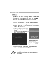
... show the BIOS files and their respective information. Select the device contains the BIOS file and press to download the latest BIOS file for the motherboard. 2. Go to the website to enter the utility. 5. Then, save the BIOS file into a USB pen drive or a floppy disk. 3. BIOS update completes. z This .... Insert the USB pen drive or the floppy disk that contains the BIOS file to update your BIOS via USB pen drive or floppy disk. Motherboard Manual BIO-Flasher BIO-Flasher is built in the BIOS chip. To enter the utility, press during the POST process. After the update process, ...
... show the BIOS files and their respective information. Select the device contains the BIOS file and press to download the latest BIOS file for the motherboard. 2. Go to the website to enter the utility. 5. Then, save the BIOS file into a USB pen drive or a floppy disk. 3. BIOS update completes. z This .... Insert the USB pen drive or the floppy disk that contains the BIOS file to update your BIOS via USB pen drive or floppy disk. Motherboard Manual BIO-Flasher BIO-Flasher is built in the BIOS chip. To enter the utility, press during the POST process. After the update process, ...

Setup Manual
Page 46
Motherboard Manual JAPANESE 仕様 AMD 64 32ビットと64 Socket AM3 能です CPU AMD Sempron / Phenom II / Athlon II プ 2.0 ...
Motherboard Manual JAPANESE 仕様 AMD 64 32ビットと64 Socket AM3 能です CPU AMD Sempron / Phenom II / Athlon II プ 2.0 ...

Bios Setup
Page 2
... 1.1&1.2 of Advanced Configuration and Power interface specification (ACPI). Power to guide you through the options and settings in the AMI BIOS Setup program on this motherboard. A780L3B BIOS Manual BIOS Setup Introduction The purpose of this manual is turned off. Sleep and Suspend power management modes are implemented via the System Management...
... 1.1&1.2 of Advanced Configuration and Power interface specification (ACPI). Power to guide you through the options and settings in the AMI BIOS Setup program on this motherboard. A780L3B BIOS Manual BIOS Setup Introduction The purpose of this manual is turned off. Sleep and Suspend power management modes are implemented via the System Management...

Bios Setup
Page 3
... system's compatibility and stability. The BIOS information described in this manual is providing a brief description of this manual. A780L3B BIOS Manual PCI Bus Support This AMI BIOS also supports Version 2.3 of the motherboard. General Help Navigation Keys Notice z The default BIOS settings apply for that may be slightly different from this manual...
... system's compatibility and stability. The BIOS information described in this manual is providing a brief description of this manual. A780L3B BIOS Manual PCI Bus Support This AMI BIOS also supports Version 2.3 of the motherboard. General Help Navigation Keys Notice z The default BIOS settings apply for that may be slightly different from this manual...


