Update Manual
Page 3
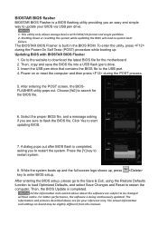
...simple way to update your reference only. Click Yes to the USB port. 4. Press the [Y] key to download the latest BIOS file for the motherboard. 2. Then, the BIOS Update is built in the BIOS ROM. The actual information and settings on or reset the computer and then press during ...the Power-On Self Tests (POST) procedure while booting up , press key to be slightly different from this manual. BIOSTAR BIOS flasher BIOSTAR BIOS Flasher is a BIOS flashing utility providing you are sure to flash the BIOS file. Go to the website to restart system. 8. Then...
...simple way to update your reference only. Click Yes to the USB port. 4. Press the [Y] key to download the latest BIOS file for the motherboard. 2. Then, the BIOS Update is built in the BIOS ROM. The actual information and settings on or reset the computer and then press during ...the Power-On Self Tests (POST) procedure while booting up , press key to be slightly different from this manual. BIOSTAR BIOS flasher BIOSTAR BIOS Flasher is a BIOS flashing utility providing you are sure to flash the BIOS file. Go to the website to restart system. 8. Then...

Setup Manual
Page 2
Table of Contents Chapter 1: Introduction 1 1.1 Before You Start 1 1.2 Package Checklist 1 1.3 Motherboard Features 2 1.4 Rear Panel Connectors 3 1.5 Motherboard Layout 4 Chapter 2: Hardware Installation 5 2.1 Installing Central Processing Unit (CPU 5 2.2 FAN Headers 7 2.3 Installing System Memory 8 2.4 Connectors and Slots 10 Chapter 3: Headers & Jumpers Setup 13 3.1 How to ...
Table of Contents Chapter 1: Introduction 1 1.1 Before You Start 1 1.2 Package Checklist 1 1.3 Motherboard Features 2 1.4 Rear Panel Connectors 3 1.5 Motherboard Layout 4 Chapter 2: Hardware Installation 5 2.1 Installing Central Processing Unit (CPU 5 2.2 FAN Headers 7 2.3 Installing System Memory 8 2.4 Connectors and Slots 10 Chapter 3: Headers & Jumpers Setup 13 3.1 How to ...

Setup Manual
Page 3
... or flex the board. „ Do not leave any unfastened small parts inside the case after installation. Before you start installing the motherboard, please make sure you follow the instructions below: „ Prepare a dry and stable working environment with sufficient lighting. „ Always...static charge. „ Avoid touching the components on the edge, do not try to area or your motherboard version. 1 A770E CHAPTER 1: INTRODUCTION 1.1 BEFORE YOU START Thank you take the motherboard out from dangerous area, such as heat source, humid air and water. „ The operating temperatures...
... or flex the board. „ Do not leave any unfastened small parts inside the case after installation. Before you start installing the motherboard, please make sure you follow the instructions below: „ Prepare a dry and stable working environment with sufficient lighting. „ Always...static charge. „ Avoid touching the components on the edge, do not try to area or your motherboard version. 1 A770E CHAPTER 1: INTRODUCTION 1.1 BEFORE YOU START Thank you take the motherboard out from dangerous area, such as heat source, humid air and water. „ The operating temperatures...
Setup Manual
Page 4
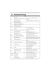
Motherboard Manual 1.3 MOTHERBOARD FEATURES CPU FSB Chipset SPEC Socket AM2+ AMD 64 Architecture enables 32 and 64 bit AMD Sempron / Athlon / Athlon II / Phenom/ computing Phenom II processors ...
Motherboard Manual 1.3 MOTHERBOARD FEATURES CPU FSB Chipset SPEC Socket AM2+ AMD 64 Architecture enables 32 and 64 bit AMD Sempron / Athlon / Athlon II / Phenom/ computing Phenom II processors ...

Setup Manual
Page 6
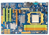
Motherboard Manual 1.5 MOTHERBOARD LAYOUT KBMS1 CPU_FAN1 ATXPWR2 JUSBV2 DIM M A 1 DIM M B 1 DIM M A 2 DIM M B 2 Socket A M2 COM1 U SB1 RJ45USB1 AT XPW R1 ID E1 AUDIO1 LAN PEX1_1 AMD 770 PEX16_1 Super I/O PEX1_2 PCI1 BAT JCMOS1 AMD BIOS SB710 SATA1 SATA3 SATA5 Codec PCI2 JS P DIFO UT1 F_A UDIO1 PCI3 F_P RINT1 F DD1 JUSBV1 F_USB1F_USB2 SATA2 SATA4 SATA6 SYS_ F AN1 PANEL1 Note: ■ represents the 1st pin. 4
Motherboard Manual 1.5 MOTHERBOARD LAYOUT KBMS1 CPU_FAN1 ATXPWR2 JUSBV2 DIM M A 1 DIM M B 1 DIM M A 2 DIM M B 2 Socket A M2 COM1 U SB1 RJ45USB1 AT XPW R1 ID E1 AUDIO1 LAN PEX1_1 AMD 770 PEX16_1 Super I/O PEX1_2 PCI1 BAT JCMOS1 AMD BIOS SB710 SATA1 SATA3 SATA5 Codec PCI2 JS P DIFO UT1 F_A UDIO1 PCI3 F_P RINT1 F DD1 JUSBV1 F_USB1F_USB2 SATA2 SATA4 SATA6 SYS_ F AN1 PANEL1 Note: ■ represents the 1st pin. 4
Setup Manual
Page 8
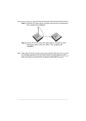
... BIOS to boot while using AM2+/AM3 CPUs. This completes the installation. In this case, please install one standard AM2 CPU to complete the installation. Motherboard Manual Step 3: Hold the CPU down firmly, and then close the lever toward direct B to boot your system, and update the latest BIOS from our...
... BIOS to boot while using AM2+/AM3 CPUs. This completes the installation. In this case, please install one standard AM2 CPU to complete the installation. Motherboard Manual Step 3: Hold the CPU down firmly, and then close the lever toward direct B to boot your system, and update the latest BIOS from our...

Setup Manual
Page 10
Insert the DIMM vertically and firmly into the slot until the retaining chip snap back in place and the DIMM is properly seated. 8 DDR2 Modules 1. Unlock a DIMM slot by pressing the retaining clips outward. Align a DIMM on the slot such that the notch on the DIMM matches the break on the Slot. 2. D IM M A1 D IM M B1 D IM M A2 D IM M B2 Motherboard Manual 2.3 INSTALLING SYSTEM MEMORY A.
Insert the DIMM vertically and firmly into the slot until the retaining chip snap back in place and the DIMM is properly seated. 8 DDR2 Modules 1. Unlock a DIMM slot by pressing the retaining clips outward. Align a DIMM on the slot such that the notch on the DIMM matches the break on the Slot. 2. D IM M A1 D IM M B1 D IM M A2 D IM M B2 Motherboard Manual 2.3 INSTALLING SYSTEM MEMORY A.

Setup Manual
Page 12
...standard floppy disk connector that supports 360K, 720K, 1.2M, 1.44M and 2.88M floppy disk types. 2 34 1 33 IDE1: Hard Disk Connector The motherboard has a 32-bit Enhanced IDE Controller that provides PIO Mode 0~4, Bus Master, Multi-word DMA, and Ultra DMA 33/66/100/133 functionality. 40 39... 2 1 SATA1~SATA6: Serial ATA Connectors The motherboard has a PCI to SATA Controller with 6 channels SATA interface, it satisfies the SATA 2.5 spec and with transfer rate of 3.0Gb/s. SATA1 SATA3 SATA5 ...
...standard floppy disk connector that supports 360K, 720K, 1.2M, 1.44M and 2.88M floppy disk types. 2 34 1 33 IDE1: Hard Disk Connector The motherboard has a 32-bit Enhanced IDE Controller that provides PIO Mode 0~4, Bus Master, Multi-word DMA, and Ultra DMA 33/66/100/133 functionality. 40 39... 2 1 SATA1~SATA6: Serial ATA Connectors The motherboard has a PCI to SATA Controller with 6 channels SATA interface, it satisfies the SATA 2.5 spec and with transfer rate of 3.0Gb/s. SATA1 SATA3 SATA5 ...

Setup Manual
Page 14
...a bus standard for an aggregate of 16GB/s totally. PEX1_1/PEX1_2: PCI-Express Gen2 x1 Slots - P EX1_1 P EX16_1 P EX1_2 PCI1~PCI3: Peripheral Component Interconnect Slots This motherboard is designated as 32 bits. Maximum theoretical realized bandwidth of 5.0Gb/s on the data pins. - 2X bandwidth over the PCI-Express 1.0 architecture. PCI1 PCI2 PCI3... 2.0 compliant. - Data transfer bandwidth up to 500MB/s per direction, for expansion cards. This PCI slot is equipped with 3 standard PCI slots. PCI-Express 2.0 compliant. - Motherboard Manual PEX16_1: PCI-Express Gen2 x16 Slot -
...a bus standard for an aggregate of 16GB/s totally. PEX1_1/PEX1_2: PCI-Express Gen2 x1 Slots - P EX1_1 P EX16_1 P EX1_2 PCI1~PCI3: Peripheral Component Interconnect Slots This motherboard is designated as 32 bits. Maximum theoretical realized bandwidth of 5.0Gb/s on the data pins. - 2X bandwidth over the PCI-Express 1.0 architecture. PCI1 PCI2 PCI3... 2.0 compliant. - Data transfer bandwidth up to 500MB/s per direction, for expansion cards. This PCI slot is equipped with 3 standard PCI slots. PCI-Express 2.0 compliant. - Motherboard Manual PEX16_1: PCI-Express Gen2 x16 Slot -

Setup Manual
Page 16
... for USB 2.0 Ports at Front Panel This header allows user to connect the front audio output cable with internal USB devices, like USB card reader. Motherboard Manual F_AUDIO1: Front Panel Audio Header This header allows user to connect additional USB cable on the PC front panel, and also can be connected...
... for USB 2.0 Ports at Front Panel This header allows user to connect the front audio output cable with internal USB devices, like USB card reader. Motherboard Manual F_AUDIO1: Front Panel Audio Header This header allows user to connect additional USB cable on the PC front panel, and also can be connected...

Setup Manual
Page 17
JUSBV1/JUSBV2: Power Source Headers for USB Ports Pin 1-2 Close: JUSBV1: +5V for USB ports at F_USB1/F_USB2. Set the jumper to avoid damaging the motherboard. 3 1 Pin 1-2 Close: Normal Operation (Default). 3 1 3 1 Pin 2-3 Close: Clear CMOS data. ※ Clear CMOS Procedures: 1. Reset your desired password... or clear the CMOS data. 15 Pin 2-3 Close: JUSBV1: +5V STB for USB ports at USB1/RJ45USB1. A770E 3 1 JUSBV2 13 Pin 1-2 close JUSBV1 13 13 Pin 2-3 close JCMOS1: Clear CMOS Header Placing the jumper on the AC. 6. Please carefully...
JUSBV1/JUSBV2: Power Source Headers for USB Ports Pin 1-2 Close: JUSBV1: +5V for USB ports at F_USB1/F_USB2. Set the jumper to avoid damaging the motherboard. 3 1 Pin 1-2 Close: Normal Operation (Default). 3 1 3 1 Pin 2-3 Close: Clear CMOS data. ※ Clear CMOS Procedures: 1. Reset your desired password... or clear the CMOS data. 15 Pin 2-3 Close: JUSBV1: +5V STB for USB ports at USB1/RJ45USB1. A770E 3 1 JUSBV2 13 Pin 1-2 close JUSBV1 13 13 Pin 2-3 close JCMOS1: Clear CMOS Header Placing the jumper on the AC. 6. Please carefully...

Setup Manual
Page 18
Motherboard Manual F_PRINT1: Printer Port Connector This header allows you to connector printer on the PC. Pin Assignment 1 -Strobe 2 -ALF 3 Data 0 4 -Error 5 Data 1 6 -Init 7 Data 2 8 -Scltin 9 Data 3 10 Ground 11 Data 4 12 Ground 13 Data 5 2 1 Pin 14 15 16 17 18 19 20 21 22 23 24 25 26 25 Assignment Ground Data 6 Ground Data 7 Ground -ACK Ground Busy Ground PE Ground SCLT Key 16
Motherboard Manual F_PRINT1: Printer Port Connector This header allows you to connector printer on the PC. Pin Assignment 1 -Strobe 2 -ALF 3 Data 0 4 -Error 5 Data 1 6 -Init 7 Data 2 8 -Scltin 9 Data 3 10 Ground 11 Data 4 12 Ground 13 Data 5 2 1 Pin 14 15 16 17 18 19 20 21 22 23 24 25 26 25 Assignment Ground Data 6 Ground Data 7 Ground -ACK Ground Busy Ground PE Ground SCLT Key 16

Setup Manual
Page 20
... databases or any other application that eliminates tedious manual backups to the other drive. Drawbacks: Requires 2 drives for the storage space of a hardware failure. Motherboard Manual RAID 1: Every read and write is actually carried out in parallel across 2 disk drives in the array.
... databases or any other application that eliminates tedious manual backups to the other drive. Drawbacks: Requires 2 drives for the storage space of a hardware failure. Motherboard Manual RAID 1: Every read and write is actually carried out in parallel across 2 disk drives in the array.

Setup Manual
Page 22
...Click on the Driver icon. Click on each software title to launch the installation program. The setup guide will auto detect your motherboard and operating system. Please download the latest version of Acrobat Reader software from the paperback manual, we also provide manual in the... Driver CD. Note: You will list the compatible driver for better system performance. Motherboard Manual CHAPTER 5: USEFUL HELP 5.1 DRIVER INSTALLATION NOTE After you installed your operating system, please insert the Fully Setup Driver CD into...
...Click on the Driver icon. Click on each software title to launch the installation program. The setup guide will auto detect your motherboard and operating system. Please download the latest version of Acrobat Reader software from the paperback manual, we also provide manual in the... Driver CD. Note: You will list the compatible driver for better system performance. Motherboard Manual CHAPTER 5: USEFUL HELP 5.1 DRIVER INSTALLATION NOTE After you installed your operating system, please insert the Fully Setup Driver CD into...

Setup Manual
Page 24
..."Send" to confirm or "Do Not Send" to the following web http://www.biostar.com.tw/app/en-us/about/contact.php for your system information while using Outlook Express as your system information including motherboard/BIOS/CPU/video/ device/OS information. If you will see your default e-mail ...dialog appears asking you may need to save this information, click "Send" to send the mail out. We will be saved to a .txt file. Motherboard Manual After filling up this information to a .txt file, click "Save As..." Go to cancel. A warning dialog would appear asking for getting our ...
..."Send" to confirm or "Do Not Send" to the following web http://www.biostar.com.tw/app/en-us/about/contact.php for your system information while using Outlook Express as your system information including motherboard/BIOS/CPU/video/ device/OS information. If you will see your default e-mail ...dialog appears asking you may need to save this information, click "Send" to send the mail out. We will be saved to a .txt file. Motherboard Manual After filling up this information to a .txt file, click "Save As..." Go to cancel. A warning dialog would appear asking for getting our ...

Setup Manual
Page 25
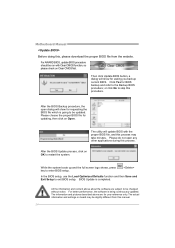
A770E BIOS Update BIOS Update is a convenient utility which allows you to save file and enter file name. (We recommend that the file name should be English/number and no longer than 7 characters.) Then click Save. Choose the position to update your motherboard BIOS under Windows system. After the saving process, finish dialog...
A770E BIOS Update BIOS Update is a convenient utility which allows you to save file and enter file name. (We recommend that the file name should be English/number and no longer than 7 characters.) Then click Save. Choose the position to update your motherboard BIOS under Windows system. After the saving process, finish dialog...
Setup Manual
Page 26
Motherboard Manual Before doing this process. After the BIOS Update process, click on Open. The information and pictures described above about the software are for updating, ...
Motherboard Manual Before doing this process. After the BIOS Update process, click on Open. The information and pictures described above about the software are for updating, ...

Setup Manual
Page 27
...with the CPU speed. Clear the CMOS data. (See "Close CMOS Header: JCMOS1" section) 2. The CPU cooler surface is over heated, the motherboard will shutdown automatically to relief the CPU protection function. 1. Remove the power cord from power supply for seconds, that means the CPU protection function ...CPU, and the system may not power on again. Power on the system again. 25 Plug in the power cord and boot up the system. A770E 5.3 EXTRA INFORMATION CPU Overheated If the system shutdown automatically after power on system for seconds. 2. Or you can: 1. In this case, please ...
...with the CPU speed. Clear the CMOS data. (See "Close CMOS Header: JCMOS1" section) 2. The CPU cooler surface is over heated, the motherboard will shutdown automatically to relief the CPU protection function. 1. Remove the power cord from power supply for seconds, that means the CPU protection function ...CPU, and the system may not power on again. Power on the system again. 25 Plug in the power cord and boot up the system. A770E 5.3 EXTRA INFORMATION CPU Overheated If the system shutdown automatically after power on system for seconds. 2. Or you can: 1. In this case, please ...

Setup Manual
Page 28
... the computer and then press during the Power-On Self Tests (POST) procedure while booting up. Press to download the latest BIOS file for the motherboard. 2. Updating BIOS with FAT32/16 format and single partition. After the update process, the utility will ask you an easy and simple way to the.... Insert the USB pen drive or the floppy disk that contains the BIOS file to update your BIOS via USB pen drive or floppy disk. Motherboard Manual BIO-Flasher BIO-Flasher is built in the BIOS chip. BIOS update completes. Then, save the BIOS file into a USB pen drive or a floppy...
... the computer and then press during the Power-On Self Tests (POST) procedure while booting up. Press to download the latest BIOS file for the motherboard. 2. Updating BIOS with FAT32/16 format and single partition. After the update process, the utility will ask you an easy and simple way to the.... Insert the USB pen drive or the floppy disk that contains the BIOS file to update your BIOS via USB pen drive or floppy disk. Motherboard Manual BIO-Flasher BIO-Flasher is built in the BIOS chip. BIOS update completes. Then, save the BIOS file into a USB pen drive or a floppy...

Setup Manual
Page 29
A770E 5.4 AMI BIOS BEEP CODE Boot Block Beep Codes Number of Beeps Description 1 No media present. (Insert diskette in floppy drive A:) 2 "AMIBOOT.ROM" file not found ..., consult your system manufacturer. Fatal error indicating a serious problem with known good modules. If the video adapter is an add-in card. Before declaring the motherboard beyond all expansion cards except the video adapter.
A770E 5.4 AMI BIOS BEEP CODE Boot Block Beep Codes Number of Beeps Description 1 No media present. (Insert diskette in floppy drive A:) 2 "AMIBOOT.ROM" file not found ..., consult your system manufacturer. Fatal error indicating a serious problem with known good modules. If the video adapter is an add-in card. Before declaring the motherboard beyond all expansion cards except the video adapter.

