Setup Manual
Page 4
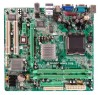
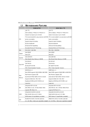
... Slots x 2 DIMM Slots x 2 Each DIMM supports 256/512MB & 1GB DDR2 Each DIMM supports 256/512MB & 1GB DDR2 Main Memory Max Memory Capacity 2GB Dual Channel Mode DDR2 memory module Supports DDR2 400 / 533 / 667 Max Memory Capacity 2GB Dual.../s auto negotiation (Gigabit 10 / 100 Mb/s / 1Gb/s auto negotiation (Gigabit 2 Data transfer rates up to 3.0 Gb/s. Motherboard Manual 1.3 MOTHERBOARD FEATURES 945GC-M7 SE 945GC Micro 775 LGA 775 LGA 775 Intel Core2Duo / Pentium 4 / Pentium D / Intel Core2Duo / Pentium 4 / Pentium D / Celeron D processor up to 3.8 GHz Celeron D processor...
... Slots x 2 DIMM Slots x 2 Each DIMM supports 256/512MB & 1GB DDR2 Each DIMM supports 256/512MB & 1GB DDR2 Main Memory Max Memory Capacity 2GB Dual Channel Mode DDR2 memory module Supports DDR2 400 / 533 / 667 Max Memory Capacity 2GB Dual.../s auto negotiation (Gigabit 10 / 100 Mb/s / 1Gb/s auto negotiation (Gigabit 2 Data transfer rates up to 3.0 Gb/s. Motherboard Manual 1.3 MOTHERBOARD FEATURES 945GC-M7 SE 945GC Micro 775 LGA 775 LGA 775 Intel Core2Duo / Pentium 4 / Pentium D / Intel Core2Duo / Pentium 4 / Pentium D / Celeron D processor up to 3.8 GHz Celeron D processor...

Setup Manual
Page 27
... when testing and results in the About panel, you do not need to install DirectX 8.1.) 25 The Overvoltage Manager, on our main panel. In addition, the frequency status of CPU, memory, VGA and PCI along with just one . 5.2 SYSTEM REQUIREMENT OS ...includes DirectX 8.1. Moreover, to protect users' computer systems if the setting is either the original system speed or a suitable one click. 945GC-M7 SE / 945GC Micro 775 CHAPTER 5: WARPSPEEDER™ III 5.1 INTRODUCTION [WarpSpeeder™ III], a new powerful control utility, features three user-friendly functions including ...
... when testing and results in the About panel, you do not need to install DirectX 8.1.) 25 The Overvoltage Manager, on our main panel. In addition, the frequency status of CPU, memory, VGA and PCI along with just one . 5.2 SYSTEM REQUIREMENT OS ...includes DirectX 8.1. Moreover, to protect users' computer systems if the setting is either the original system speed or a suitable one click. 945GC-M7 SE / 945GC Micro 775 CHAPTER 5: WARPSPEEDER™ III 5.1 INTRODUCTION [WarpSpeeder™ III], a new powerful control utility, features three user-friendly functions including ...

Setup Manual
Page 29
5.4 WARPSPEEDER™ III 945GC-M7 SE / 945GC Micro 775 1. Main Panel contains features as follows: a. The On/Off button is Main Panel. Please refer to the following figure; Contains About, Voltage/Overclock, and Hardware Monitor Buttons for closing the program. 27 ... and PCI clock information. Desktop Icon: After the [WarpSpeeder™ III] has been installed, a [WarpSpeeder™ III] icon will be launched. b. Main Panel If you double-click the desktop icon, [WarpSpeeder™ III] will appear on the desktop, just like the icon shown below. the utility's first...
5.4 WARPSPEEDER™ III 945GC-M7 SE / 945GC Micro 775 1. Main Panel contains features as follows: a. The On/Off button is Main Panel. Please refer to the following figure; Contains About, Voltage/Overclock, and Hardware Monitor Buttons for closing the program. 27 ... and PCI clock information. Desktop Icon: After the [WarpSpeeder™ III] has been installed, a [WarpSpeeder™ III] icon will be launched. b. Main Panel If you double-click the desktop icon, [WarpSpeeder™ III] will appear on the desktop, just like the icon shown below. the utility's first...

Setup Manual
Page 30
As you can see, the Overclock Panel is on the right side, and the Overvoltage Panel is on the left side. 28 Overclock/Overvoltage Panel Click the Overclock/Overvoltage button in the Main Panel, the button will be highlighted and the Overclock/Overvoltage Panel will show up as the following figure. Motherboard Manual 3.
As you can see, the Overclock Panel is on the right side, and the Overvoltage Panel is on the left side. 28 Overclock/Overvoltage Panel Click the Overclock/Overvoltage button in the Main Panel, the button will be highlighted and the Overclock/Overvoltage Panel will show up as the following figure. Motherboard Manual 3.

Setup Manual
Page 32
... following figure. In this panel, you can get the real-time status information of your system. Hardware Monitor Panel Click the Hardware Monitor button in Main Panel, the button will be highlighted and the Hardware Monitor panel will be refreshed every 1 second. 30 Click on "+" to increase or "-" to adjust CPU...
... following figure. In this panel, you can get the real-time status information of your system. Hardware Monitor Panel Click the Hardware Monitor button in Main Panel, the button will be highlighted and the Hardware Monitor panel will be refreshed every 1 second. 30 Click on "+" to increase or "-" to adjust CPU...

Setup Manual
Page 33
... highlighted and the About Panel will not interfere other panels' functions. In this panel, you can also get model name and detail information in Main Panel, the button will be disabled, but will show up as the following figure. Note: Because the overclock, overvoltage, and hardware monitor features...by several separate chipset, [WarpSpeeder™ III] divide these features to overclocking. This property can make [WarpSpeeder™ III] utility more robust. 31 945GC-M7 SE / 945GC Micro 775 5. About Panel Click the "about" button in hints of [WarpSpeeder™ III] utility.
... highlighted and the About Panel will not interfere other panels' functions. In this panel, you can also get model name and detail information in Main Panel, the button will be disabled, but will show up as the following figure. Note: Because the overclock, overvoltage, and hardware monitor features...by several separate chipset, [WarpSpeeder™ III] divide these features to overclocking. This property can make [WarpSpeeder™ III] utility more robust. 31 945GC-M7 SE / 945GC Micro 775 5. About Panel Click the "about" button in hints of [WarpSpeeder™ III] utility.

Setup Manual
Page 52
945GC-M7 SE / 945GC Micro 775 BIOS SETUP BIOS Setup 1 1 Main Menu...3 2 Standard CMOS Features 6 3 Advanced BIOS Features 8 4 Advanced Chipset Features 14 5 Integrated Peripherals 18 6 Power Management Setup 23 7 PnP/PCI Configurations 28 8 PC Health Status 30 9 Performance Booster Zone 32 i
945GC-M7 SE / 945GC Micro 775 BIOS SETUP BIOS Setup 1 1 Main Menu...3 2 Standard CMOS Features 6 3 Advanced BIOS Features 8 4 Advanced Chipset Features 14 5 Integrated Peripherals 18 6 Power Management Setup 23 7 PnP/PCI Configurations 28 8 PC Health Status 30 9 Performance Booster Zone 32 i

Setup Manual
Page 54
... keys to highlight items, press to select, use the and keys to change entries, press for help on the right (menu bar) Move to Main Menu General help and press to navigate in the Setup program by using the keyboard. Quit and not save changes into CMOS Status Page Setup...make changes Increase the numeric value or make changes Decrease the numeric value or make changes Main Menu - Keystroke Up arrow Down arrow Left arrow Right arrow Move Enter PgUp key PgDn key + Key - 945GC-M7 SE / 945GC Micro 775 PCI Bus Support This PHOENIX-AWARD BIOS also supports Version 3.0 of the Intel PCI (...
... keys to highlight items, press to select, use the and keys to change entries, press for help on the right (menu bar) Move to Main Menu General help and press to navigate in the Setup program by using the keyboard. Quit and not save changes into CMOS Status Page Setup...make changes Increase the numeric value or make changes Decrease the numeric value or make changes Main Menu - Keystroke Up arrow Down arrow Left arrow Right arrow Move Enter PgUp key PgDn key + Key - 945GC-M7 SE / 945GC Micro 775 PCI Bus Support This PHOENIX-AWARD BIOS also supports Version 3.0 of the Intel PCI (...

Setup Manual
Page 55
... industry standard configurable options. WARNING !! Advanced Chipset Features This submenu allows you to select from several setup functions. 945GC-M7 SE / 945GC Micro 775 1 Main Menu Once you enter Phoenix-Award BIOS™ CMOS Setup Utility, the Main Menu will appear on board, for reference, please refer to the BIOS installed on the screen. Advanced BIOS...
... industry standard configurable options. WARNING !! Advanced Chipset Features This submenu allows you to select from several setup functions. 945GC-M7 SE / 945GC Micro 775 1 Main Menu Once you enter Phoenix-Award BIOS™ CMOS Setup Utility, the Main Menu will appear on board, for reference, please refer to the BIOS installed on the screen. Advanced BIOS...

Setup Manual
Page 58
... This table shows the selections that the 'Day' automatically changes when you can make on the Main Menu. IDE Channel 0 Master Options are in each item. „ Figure 2. sub menu of detailed options. 6 945GC-M7 SE / 945GC Micro 775 2 Standard CMOS Features The items in Standard CMOS Setup Menu are in its sub Press to...
... This table shows the selections that the 'Day' automatically changes when you can make on the Main Menu. IDE Channel 0 Master Options are in each item. „ Figure 2. sub menu of detailed options. 6 945GC-M7 SE / 945GC Micro 775 2 Standard CMOS Features The items in Standard CMOS Setup Menu are in its sub Press to...

Setup Manual
Page 65
...EPA) Show This item allows you to enable/disable the summary screen. Disab led No "Small Logo" shows when system boots up . 945GC-M7 SE / 945GC Micro 775 Typematic Delay (Msec) Sets the delay time after the key is required to access the Setup Utility only. APIC Mode Selecting Enabled enables ...APIC device mode reporting from the Setup main menu. OS Select For DRAM > 64MB A choice other than Non-OS2 is also required to...
...EPA) Show This item allows you to enable/disable the summary screen. Disab led No "Small Logo" shows when system boots up . 945GC-M7 SE / 945GC Micro 775 Typematic Delay (Msec) Sets the delay time after the key is required to access the Setup Utility only. APIC Mode Selecting Enabled enables ...APIC device mode reporting from the Setup main menu. OS Select For DRAM > 64MB A choice other than Non-OS2 is also required to...