
Setup Manual
Page 1
There is not allowed without notice and we will not occur in this user's manual is subject to Part 15 of this user's manual. 945GC-M7 SE / 945GC Micro 775 Setup Manual FCC Information and Copyright This equipment has been tested and found in a particular installation. Duplication of this publication, in part or in writing. ...
There is not allowed without notice and we will not occur in this user's manual is subject to Part 15 of this user's manual. 945GC-M7 SE / 945GC Micro 775 Setup Manual FCC Information and Copyright This equipment has been tested and found in a particular installation. Duplication of this publication, in part or in writing. ...
Setup Manual
Page 2
... Contents Chapter 1: Introduction 1 1.1 Before You Start 1 1.2 Package Checklist 1 1.3 Motherboard Features 2 1.4 Rear Panel Connectors (for Ver 6.x 4 1.5 Rear Panel Connectors (for Ver 5.x 4 1.6 Motherboard Layout (for 945GC-M7 SE 5 1.7 Motherboard Layout (for 945GC Micro 775 6 Chapter 2: Hardware Installation 7 2.1 Installing Central Processing Unit (CPU 7 2.2 FAN Headers 9 2.3 Installing System Memory 10 2.4 Connectors and Slots 12 Chapter 3: Headers & Jumpers Setup 14...
... Contents Chapter 1: Introduction 1 1.1 Before You Start 1 1.2 Package Checklist 1 1.3 Motherboard Features 2 1.4 Rear Panel Connectors (for Ver 6.x 4 1.5 Rear Panel Connectors (for Ver 5.x 4 1.6 Motherboard Layout (for 945GC-M7 SE 5 1.7 Motherboard Layout (for 945GC Micro 775 6 Chapter 2: Hardware Installation 7 2.1 Installing Central Processing Unit (CPU 7 2.2 FAN Headers 9 2.3 Installing System Memory 10 2.4 Connectors and Slots 12 Chapter 3: Headers & Jumpers Setup 14...
Setup Manual
Page 3
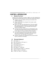
... use grounded wrist strap to remove the static charge. „ Avoid touching the components on motherboard or the rear side of the board unless necessary. 945GC-M7 SE / 945GC Micro 775 CHAPTER 1: INTRODUCTION 1.1 BEFORE YOU START Thank you take the motherboard out from anti-static bag, ground yourself properly by touching any unfastened small parts...
... use grounded wrist strap to remove the static charge. „ Avoid touching the components on motherboard or the rear side of the board unless necessary. 945GC-M7 SE / 945GC Micro 775 CHAPTER 1: INTRODUCTION 1.1 BEFORE YOU START Thank you take the motherboard out from anti-static bag, ground yourself properly by touching any unfastened small parts...
Setup Manual
Page 4
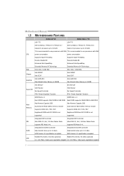
...Extended Memory 64 Technology FSB 533 / 800 / 1066 MHz 533 / 800 / 1066 MHz Chipset Intel 945GC Intel ICH7 Intel 945GC Intel ICH7 Graphics Intel GMA 950 Max Shared Video Memory is 224MB Intel GMA 950 Max Shared Video ... Mb/s / 1Gb/s auto negotiation (Gigabit 10 / 100 Mb/s / 1Gb/s auto negotiation (Gigabit 2 SATA Version 2.0 specification compliant. Motherboard Manual 1.3 MOTHERBOARD FEATURES 945GC-M7 SE 945GC Micro 775 LGA 775 LGA 775 Intel Core2Duo / Pentium 4 / Pentium D / Intel Core2Duo / Pentium 4 / Pentium D / Celeron D processor up to 3.8 GHz Celeron D processor up to...
...Extended Memory 64 Technology FSB 533 / 800 / 1066 MHz 533 / 800 / 1066 MHz Chipset Intel 945GC Intel ICH7 Intel 945GC Intel ICH7 Graphics Intel GMA 950 Max Shared Video Memory is 224MB Intel GMA 950 Max Shared Video ... Mb/s / 1Gb/s auto negotiation (Gigabit 10 / 100 Mb/s / 1Gb/s auto negotiation (Gigabit 2 SATA Version 2.0 specification compliant. Motherboard Manual 1.3 MOTHERBOARD FEATURES 945GC-M7 SE 945GC Micro 775 LGA 775 LGA 775 Intel Core2Duo / Pentium 4 / Pentium D / Intel Core2Duo / Pentium 4 / Pentium D / Celeron D processor up to 3.8 GHz Celeron D processor up to...

Setup Manual
Page 5
945GC-M7 SE / 945GC Micro 775 945GC-M7 SE bandwidth is for RTL 8110SC only) Half / Full duplex capability Sound Codec ALC662(Ver 6.x) 5.1 channels audio out (Ver 6.x) High-Definition Audio support PCI Express x16 ... Port x4 Audio Jack (Ver 6.x) x3 Board Size 219 (W) x 235 (L) mm Windows 2000 / XP / VISTA OS Support Biostar Reserves the right to add or remove support for any OS with or without notice. 945GC Micro 775 bandwidth is for RTL 8110SC only) Half / Full duplex capability ALC861VD(Ver 6.x) / ALC888(Ver 5.x) 5.1 channels audio out (Ver...
945GC-M7 SE / 945GC Micro 775 945GC-M7 SE bandwidth is for RTL 8110SC only) Half / Full duplex capability Sound Codec ALC662(Ver 6.x) 5.1 channels audio out (Ver 6.x) High-Definition Audio support PCI Express x16 ... Port x4 Audio Jack (Ver 6.x) x3 Board Size 219 (W) x 235 (L) mm Windows 2000 / XP / VISTA OS Support Biostar Reserves the right to add or remove support for any OS with or without notice. 945GC Micro 775 bandwidth is for RTL 8110SC only) Half / Full duplex capability ALC861VD(Ver 6.x) / ALC888(Ver 5.x) 5.1 channels audio out (Ver...
Setup Manual
Page 6
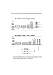
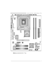
... to the audio port, please use the Line In (blue) and Mic In (Pink) audio jack. 4 Motherboard Manual 1.4 REAR PANEL CONNECTORS (FOR VER 6.X) PS/2 Mo u se LAN PS/2 K ey bo ard COM1 VGA1 USBX2 USBX2 Line In/ S urro un d Line Out Mic In 1/ Bass/ Center 1.5 REAR PANEL CONNECTORS (FOR VER 5.X) PS...
... to the audio port, please use the Line In (blue) and Mic In (Pink) audio jack. 4 Motherboard Manual 1.4 REAR PANEL CONNECTORS (FOR VER 6.X) PS/2 Mo u se LAN PS/2 K ey bo ard COM1 VGA1 USBX2 USBX2 Line In/ S urro un d Line Out Mic In 1/ Bass/ Center 1.5 REAR PANEL CONNECTORS (FOR VER 5.X) PS...
Setup Manual
Page 7
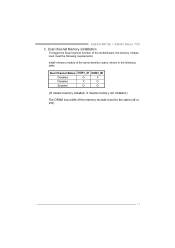
JCMOS1 Intel ICH7 BAT1 JSFAN1 SATA3 SATA1 JUSB3 JUSB4 SATA4 SATA2 JPANEL1 5 945GC-M7 SE / 945GC Micro 775 1.6 MOTHERBOARD LAYOUT (FOR 945GC-M7 SE) JKBMS1 JATXPWR2 LGA775 COJMC1OM1 CPU1 JVGA1 DDR2_A1 DDR2_B1 IDE1 FDD1 JPRNT1 JATXPWR1 JUSB2 JRJ45USB1 JCFAN1 Intel 945GC JAUDIOF1 JAUDIO1 Super I/O PEX16_1 Co dec PEX1_1 BIOS JCDIN1 LAN JSPDIF_OUT PCI1 PCI2 Note: ■ represents the 1st pin.
JCMOS1 Intel ICH7 BAT1 JSFAN1 SATA3 SATA1 JUSB3 JUSB4 SATA4 SATA2 JPANEL1 5 945GC-M7 SE / 945GC Micro 775 1.6 MOTHERBOARD LAYOUT (FOR 945GC-M7 SE) JKBMS1 JATXPWR2 LGA775 COJMC1OM1 CPU1 JVGA1 DDR2_A1 DDR2_B1 IDE1 FDD1 JPRNT1 JATXPWR1 JUSB2 JRJ45USB1 JCFAN1 Intel 945GC JAUDIOF1 JAUDIO1 Super I/O PEX16_1 Co dec PEX1_1 BIOS JCDIN1 LAN JSPDIF_OUT PCI1 PCI2 Note: ■ represents the 1st pin.

Setup Manual
Page 9
Pin-Cap Step 1: Pull the socket locking lever out from the socket and then raise the lever up to ensure pin legs won't be damaged. When the CPU is removed, cover the Pin Cap on the empty socket to a 90-degree angle. 7 945GC-M7 SE / 945GC Micro 775 CHAPTER 2: HARDWARE INSTALLATION 2.1 INSTALLING CENTRAL PROCESSING UNIT (CPU) Special Notice: Remove Pin Cap before installation, and make good preservation for future use.
Pin-Cap Step 1: Pull the socket locking lever out from the socket and then raise the lever up to ensure pin legs won't be damaged. When the CPU is removed, cover the Pin Cap on the empty socket to a 90-degree angle. 7 945GC-M7 SE / 945GC Micro 775 CHAPTER 2: HARDWARE INSTALLATION 2.1 INSTALLING CENTRAL PROCESSING UNIT (CPU) Special Notice: Remove Pin Cap before installation, and make good preservation for future use.

Setup Manual
Page 11
945GC-M7 SE / 945GC Micro 775 2.2 FAN HEADERS These fan headers support cooling-fans built in the computer. JCFAN1: CPU Fan Header JCFA N1 Pin Assignment 1 1 Ground 2 +12V 4 3 FAN RPM rate ...
945GC-M7 SE / 945GC Micro 775 2.2 FAN HEADERS These fan headers support cooling-fans built in the computer. JCFAN1: CPU Fan Header JCFA N1 Pin Assignment 1 1 Ground 2 +12V 4 3 FAN RPM rate ...
Setup Manual
Page 13
Dual Channel Status DDR2_A1 DDR2_B1 Disabled O X Disabled X O Enabled O O (O means memory installed, X means memory not installed.) The DRAM bus width of the memory module must meet the following requirements: Install memory module of the motherboard, the memory module must be the same (x8 or x16) 11 Dual Channel Memory installation To trigger the Dual Channel function of the same density in pairs, shown in the following table. 945GC-M7 SE / 945GC Micro 775 C.
Dual Channel Status DDR2_A1 DDR2_B1 Disabled O X Disabled X O Enabled O O (O means memory installed, X means memory not installed.) The DRAM bus width of the memory module must meet the following requirements: Install memory module of the motherboard, the memory module must be the same (x8 or x16) 11 Dual Channel Memory installation To trigger the Dual Channel function of the same density in pairs, shown in the following table. 945GC-M7 SE / 945GC Micro 775 C.
Setup Manual
Page 15
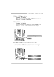
... traditional PCI architecture. PEX1_1: PCI-Express x1 Slot - PCI1 PCI2 13 PCI-Express 1.0a compliant. - PCI-Express supports a raw bit-rate of 8GB/s totally. 945GC-M7 SE / 945GC Micro 775 PEX16_1: PCI-Express x16 Slot - PEX1_1 PEX16_1 PCI1~PCI2: Peripheral Component Interconnect Slots The motherboard is designated as 32 bits. Data transfer bandwidth up to...
... traditional PCI architecture. PEX1_1: PCI-Express x1 Slot - PCI1 PCI2 13 PCI-Express 1.0a compliant. - PCI-Express supports a raw bit-rate of 8GB/s totally. 945GC-M7 SE / 945GC Micro 775 PEX16_1: PCI-Express x16 Slot - PEX1_1 PEX16_1 PCI1~PCI2: Peripheral Component Interconnect Slots The motherboard is designated as 32 bits. Data transfer bandwidth up to...

Setup Manual
Page 17
945GC-M7 SE / 945GC Micro 775 JATXPWR1: ATX Power Source Connector This connector allows user to CPU power circuit. 2 1 3 4 Pin Assignment 1 +12V 2 +12V 3 Ground 4 Ground 15 Pin Assignment 1 +3.3V 2 +3.3V 3 Ground 4 +...
945GC-M7 SE / 945GC Micro 775 JATXPWR1: ATX Power Source Connector This connector allows user to CPU power circuit. 2 1 3 4 Pin Assignment 1 +12V 2 +12V 3 Ground 4 Ground 15 Pin Assignment 1 +3.3V 2 +3.3V 3 Ground 4 +...

Setup Manual
Page 19
It will disable the output on back panel audio connectors. 945GC-M7 SE 945GC Mic ro 775 9 1 10 2 Pin Assignment 1 Mic Left in 2 Ground 3 Mic Right in 4 GPIO 5 Right line in 6 Jack Sense 7 Front Sense 8 Key 9 Left line in 10 Jack Sense 1 2 9 10 17 945GC-M7 SE / 945GC Micro 775 JSPDIF_OUT: Digital Audio out Connectors This connector allows user to connect the PCI bracket SPDIF output header. 13 Pin Assignment 1 +5V 2 SPDIF_OUT1 3 Ground JAUDIOF1: Front Panel Audio Header This header allows user to connect the front audio output cable with the PC front panel.
It will disable the output on back panel audio connectors. 945GC-M7 SE 945GC Mic ro 775 9 1 10 2 Pin Assignment 1 Mic Left in 2 Ground 3 Mic Right in 4 GPIO 5 Right line in 6 Jack Sense 7 Front Sense 8 Key 9 Left line in 10 Jack Sense 1 2 9 10 17 945GC-M7 SE / 945GC Micro 775 JSPDIF_OUT: Digital Audio out Connectors This connector allows user to connect the PCI bracket SPDIF output header. 13 Pin Assignment 1 +5V 2 SPDIF_OUT1 3 Ground JAUDIOF1: Front Panel Audio Header This header allows user to connect the front audio output cable with the PC front panel.

Setup Manual
Page 21
... 1-2 Close: JUSBV1: +5V for USB ports at JRJ45USB1/JUSB2. JUSBV3_1: +5V for USB ports at front panel (JUSB3/JUSB4). 945GC-M7 SE / 945GC Micro 775 JKBV1: Power Source Header for PS/2 Keyboard and Mouse (Only for 945GC Micro 775) 13 1 3 Pin 1-2 Close +5V for PS/2 keyboard and mouse. 1 3 Pin 2-3 close Note: In order to support this function "Power...
... 1-2 Close: JUSBV1: +5V for USB ports at JRJ45USB1/JUSB2. JUSBV3_1: +5V for USB ports at front panel (JUSB3/JUSB4). 945GC-M7 SE / 945GC Micro 775 JKBV1: Power Source Header for PS/2 Keyboard and Mouse (Only for 945GC Micro 775) 13 1 3 Pin 1-2 Close +5V for PS/2 keyboard and mouse. 1 3 Pin 2-3 close Note: In order to support this function "Power...
Setup Manual
Page 23
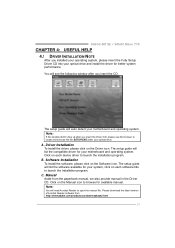
... also provide manual in the Driver CD. Click on each device driver to locate and execute the file SETUP.EXE under your optical drive. C. A. 945GC-M7 SE / 945GC Micro 775 CHAPTER 4: USEFUL HELP 4.1 DRIVER INSTALLATION NOTE After you installed your operating system, please insert the Fully Setup Driver CD into your optical drive and install...
... also provide manual in the Driver CD. Click on each device driver to locate and execute the file SETUP.EXE under your optical drive. C. A. 945GC-M7 SE / 945GC Micro 775 CHAPTER 4: USEFUL HELP 4.1 DRIVER INSTALLATION NOTE After you installed your operating system, please insert the Fully Setup Driver CD into your optical drive and install...
Setup Manual
Page 25
... to avoid a damage of the CPU, and the system may not power on again. Plug in the power cord and boot up the system. 945GC-M7 SE / 945GC Micro 775 B. CPU Overheated If the system shutdown automatically after power on the system again. 23 Remove the power cord from power supply for seconds, that means...
... to avoid a damage of the CPU, and the system may not power on again. Plug in the power cord and boot up the system. 945GC-M7 SE / 945GC Micro 775 B. CPU Overheated If the system shutdown automatically after power on the system again. 23 Remove the power cord from power supply for seconds, that means...

Setup Manual
Page 27
...addition, the frequency status of CPU, memory, VGA and PCI along with just one . 5.2 SYSTEM REQUIREMENT OS Support: Windows 98 SE, Windows Me, Windows 2000, Windows XP, Windows Vista DirectX: DirectX 8.1 or above. (The Windows XP operating system includes DirectX 8.1.... technology assures the system stability by automatically rebooting the computer and then restart to power up CPU core voltage and Memory voltage. 945GC-M7 SE / 945GC Micro 775 CHAPTER 5: WARPSPEEDER™ III 5.1 INTRODUCTION [WarpSpeeder™ III], a new powerful control utility, features three user-friendly functions ...
...addition, the frequency status of CPU, memory, VGA and PCI along with just one . 5.2 SYSTEM REQUIREMENT OS Support: Windows 98 SE, Windows Me, Windows 2000, Windows XP, Windows Vista DirectX: DirectX 8.1 or above. (The Windows XP operating system includes DirectX 8.1.... technology assures the system stability by automatically rebooting the computer and then restart to power up CPU core voltage and Memory voltage. 945GC-M7 SE / 945GC Micro 775 CHAPTER 5: WARPSPEEDER™ III 5.1 INTRODUCTION [WarpSpeeder™ III], a new powerful control utility, features three user-friendly functions ...

Setup Manual
Page 29
... simply by double-clicking the desktop icon. 2. Display the CPU Speed, CPU external clock, Memory clock, VGA clock, and PCI clock information. 5.4 WARPSPEEDER™ III 945GC-M7 SE / 945GC Micro 775 1. Contains About, Voltage/Overclock, and Hardware Monitor Buttons for closing the program. 27 Desktop Icon: After the [WarpSpeeder™ III] has been installed, a [WarpSpeeder...
... simply by double-clicking the desktop icon. 2. Display the CPU Speed, CPU external clock, Memory clock, VGA clock, and PCI clock information. 5.4 WARPSPEEDER™ III 945GC-M7 SE / 945GC Micro 775 1. Contains About, Voltage/Overclock, and Hardware Monitor Buttons for closing the program. 27 Desktop Icon: After the [WarpSpeeder™ III] has been installed, a [WarpSpeeder...

Setup Manual
Page 31
... hardware default setting. 29 c. Or, you can just click Auto overclock button and let [WarpSpeeder™ III] automatically gets the best result for current frequency. 945GC-M7 SE / 945GC Micro 775 Overclock Panel contains these features: a. If the testing is over 110 %. After reboot, the [WarpSpeeder™ III] utility will restore to adjust the CPU...
... hardware default setting. 29 c. Or, you can just click Auto overclock button and let [WarpSpeeder™ III] automatically gets the best result for current frequency. 945GC-M7 SE / 945GC Micro 775 Overclock Panel contains these features: a. If the testing is over 110 %. After reboot, the [WarpSpeeder™ III] utility will restore to adjust the CPU...

Setup Manual
Page 33
... chipset, [WarpSpeeder™ III] divide these features to overclocking. You can also get model name and detail information in hints of [WarpSpeeder™ III] utility. 945GC-M7 SE / 945GC Micro 775 5. In this panel, you can make [WarpSpeeder™ III] utility more robust. 31
... chipset, [WarpSpeeder™ III] divide these features to overclocking. You can also get model name and detail information in hints of [WarpSpeeder™ III] utility. 945GC-M7 SE / 945GC Micro 775 5. In this panel, you can make [WarpSpeeder™ III] utility more robust. 31