
DCP10 User Manual
Page 2
... Mechanical Arm 12 LED Light Switch 13 Infrared Sensor 13 Anti-glare Sheet 13 External Memory Storage 14 Insert an SD Card 14 Insert a USB Flash Drive 14 OSD MENU 15 Select Menu and Settings 16 Basic 16 Brightness 16 Contrast 16 Auto Image 16 MODE 17 Focus 17 Effect 17 Default 17 Advanced 18 Exposure 18 White Balance 18 Flicker 18 Night View 19 Presentation...
... Mechanical Arm 12 LED Light Switch 13 Infrared Sensor 13 Anti-glare Sheet 13 External Memory Storage 14 Insert an SD Card 14 Insert a USB Flash Drive 14 OSD MENU 15 Select Menu and Settings 16 Basic 16 Brightness 16 Contrast 16 Auto Image 16 MODE 17 Focus 17 Effect 17 Default 17 Advanced 18 Exposure 18 White Balance 18 Flicker 18 Night View 19 Presentation...
DCP10 User Manual
Page 4
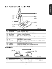
... switch. Focus the image in monophonic. On off among 3 different light settings. The recorded sound will be in the camera. Record audio when recording video clip. Easy access to a computer using a USB cable. 2 Receive remote control commands. Connections for power and external display device. Extendable for audio video recording directly to a USB flash drive and left (◄) when connecting DCP10 to various functions. ENGLISH Get Familiar with the DCP10 (6) (1) (7) (2) (8) (3) (4) (5) Name (1) Camera head (2) LED light switch (3) Camera lens (4) Control panel...
... switch. Focus the image in monophonic. On off among 3 different light settings. The recorded sound will be in the camera. Record audio when recording video clip. Easy access to a computer using a USB cable. 2 Receive remote control commands. Connections for power and external display device. Extendable for audio video recording directly to a USB flash drive and left (◄) when connecting DCP10 to various functions. ENGLISH Get Familiar with the DCP10 (6) (1) (7) (2) (8) (3) (4) (5) Name (1) Camera head (2) LED light switch (3) Camera lens (4) Control panel...

DCP10 User Manual
Page 5
... (2) USB Flash Drive port (3) Power button Rear Panel Function Insert a USB flash drive for centralized control if desire. Turn the unit on/standby mode. (1) Name (1) DC12V / LIGHTBOX port (2) DVI-I OUTPUT ports. 3 Connect the DCP10 to any display device with a USB cable and use DCP10 as a USB Camera or transfer the captured images/videos either from the camera to computer. Input the signal from RS232/CVBS (via RCA connection), and RGB to the RGB OUTPUT port only. Connect the supplied RS...
... (2) USB Flash Drive port (3) Power button Rear Panel Function Insert a USB flash drive for centralized control if desire. Turn the unit on/standby mode. (1) Name (1) DC12V / LIGHTBOX port (2) DVI-I OUTPUT ports. 3 Connect the DCP10 to any display device with a USB cable and use DCP10 as a USB Camera or transfer the captured images/videos either from the camera to computer. Input the signal from RS232/CVBS (via RCA connection), and RGB to the RGB OUTPUT port only. Connect the supplied RS...

DCP10 User Manual
Page 6
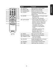
... (11) AUTO FOCUS (12) Built-in Playback mode and OSD menu. - Make a selection in MIC (7) (8) (9) (10) ( 11 ) (12 ) (fig. 1.5) Function Open and exit the OSD menu. Start/Stop audio & video recording. Adjust the focus automatically. Audio and video recording can be saved on a SD card or an USB Flash drive only. See External Memory Storage. - Switch between Camera and Computer. - View & playback captured still images and audio video files. - Use ▲...
... (11) AUTO FOCUS (12) Built-in Playback mode and OSD menu. - Make a selection in MIC (7) (8) (9) (10) ( 11 ) (12 ) (fig. 1.5) Function Open and exit the OSD menu. Start/Stop audio & video recording. Adjust the focus automatically. Audio and video recording can be saved on a SD card or an USB Flash drive only. See External Memory Storage. - Switch between Camera and Computer. - View & playback captured still images and audio video files. - Use ▲...

DCP10 User Manual
Page 7
.... (24) (8) - PC mode displays the video signal (23) (9) from the RGB INPUT port of the screen in Camera mode. (8) SLIDE SHOW Start/Stop automatically showing the captured picture/video one-by-one. (9) EFFECT Convert and display the image in BW, Negative or Color in Camera and Playback mode only. (10) CAPTURE Capture still image in Playback mode. (13) AUTO IMAGE Automatically adjust and set the white balance and exposure setting. (14) BRIGHTNESS +/- One...
.... (24) (8) - PC mode displays the video signal (23) (9) from the RGB INPUT port of the screen in Camera mode. (8) SLIDE SHOW Start/Stop automatically showing the captured picture/video one-by-one. (9) EFFECT Convert and display the image in BW, Negative or Color in Camera and Playback mode only. (10) CAPTURE Capture still image in Playback mode. (13) AUTO IMAGE Automatically adjust and set the white balance and exposure setting. (14) BRIGHTNESS +/- One...
DCP10 User Manual
Page 8
...) (13) and OSD menu. - Make a selection in camera and picture playback mode. (22) (10) (19) ENTER - Adjust the focus automatically. (23) FREEZE / STOP - Freeze live mode or in live images. - Use ◄ &► to 100%. (25) (6) (18) ZOOM +/- Move the QBOX frame and QVISOR screen cover. (fig. 1.6) (21) MENU (22) AUTO FOCUS Open and exit the OSD menu. Start/Pause video playback. (19) (20 - Use ▲&▼ to increase...
...) (13) and OSD menu. - Make a selection in camera and picture playback mode. (22) (10) (19) ENTER - Adjust the focus automatically. (23) FREEZE / STOP - Freeze live mode or in live images. - Use ◄ &► to 100%. (25) (6) (18) ZOOM +/- Move the QBOX frame and QVISOR screen cover. (fig. 1.6) (21) MENU (22) AUTO FOCUS Open and exit the OSD menu. Start/Pause video playback. (19) (20 - Use ▲&▼ to increase...
DCP10 User Manual
Page 9
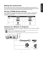
... signal using RCA connection. (see fig. 1.4 # 6) Switch DCP10 Port Display Device Port RGB RGB OUTPUT RGB INPUT TV DVI-I OUTPUT To RS232/CVBS (use RS-232/CVBS cable) DVI-I INPUT VIDEO IN Connect to a Monitor or Projector Locate the RGB (VGA) input port of the graphics display device and connect it to RGB. Make sure the TV/RGB switch is set to RGB OUTPUT port of DCP10. Set the TV-RGB Switch Setting The TV-RGB switch determines the display...
... signal using RCA connection. (see fig. 1.4 # 6) Switch DCP10 Port Display Device Port RGB RGB OUTPUT RGB INPUT TV DVI-I OUTPUT To RS232/CVBS (use RS-232/CVBS cable) DVI-I INPUT VIDEO IN Connect to a Monitor or Projector Locate the RGB (VGA) input port of the graphics display device and connect it to RGB. Make sure the TV/RGB switch is set to RGB OUTPUT port of DCP10. Set the TV-RGB Switch Setting The TV-RGB switch determines the display...

DCP10 User Manual
Page 10
... or Video equipment (i.e., VCR) to record your presentation and connect it to DVI-I input port of the display device and connect it to RCA jack of DCP10. LCD Monitor with DVI-I interface Locate the DVI-I OUTPUT port of RS-232/CVBS cable. Projector RS-232/CVBS cable INPUT VIDEO RCA cable Te l e v i s i o n VCR SCART RCA to RGB. Make sure the TV/RGB switch is set to SCART cable (not supplied) 8
... or Video equipment (i.e., VCR) to record your presentation and connect it to DVI-I input port of the display device and connect it to RCA jack of DCP10. LCD Monitor with DVI-I interface Locate the DVI-I OUTPUT port of RS-232/CVBS cable. Projector RS-232/CVBS cable INPUT VIDEO RCA cable Te l e v i s i o n VCR SCART RCA to RGB. Make sure the TV/RGB switch is set to SCART cable (not supplied) 8
DCP10 User Manual
Page 11
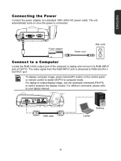
... Power Connect the power adapter to RGB INPUT port of DCP10. The unit automatically turns on the control panel or remote control to switch DCP10 to RGB and DVI-I OUTPUT port. - To display computer image, press Camera/PC button on once the power is streamed to computer mode. - Power adapter Power cord Wall outlet Connect to a Computer Locate the RGB (VGA) output port of the computer or laptop and connect it to a standard 100V~240V AC power outlet. For laptop to output display image, use...
... Power Connect the power adapter to RGB INPUT port of DCP10. The unit automatically turns on the control panel or remote control to switch DCP10 to RGB and DVI-I OUTPUT port. - To display computer image, press Camera/PC button on once the power is streamed to computer mode. - Power adapter Power cord Wall outlet Connect to a Computer Locate the RGB (VGA) output port of the computer or laptop and connect it to a standard 100V~240V AC power outlet. For laptop to output display image, use...

DCP10 User Manual
Page 12
... USB port of the computer or laptop and connect it to port. Also see fig. 1.2 #1) is connected. The built-in monophonic sound. This enables you to use DCP10 as a USB Camera or to transfer the captured pictures/videos from DCP10 to computer. Make sure the USB Flash Drive switch (see "Transfer File from the memory and to PC". The recorded audio will be in microphone on the control panel...
... USB port of the computer or laptop and connect it to port. Also see fig. 1.2 #1) is connected. The built-in monophonic sound. This enables you to use DCP10 as a USB Camera or to transfer the captured pictures/videos from DCP10 to computer. Make sure the USB Flash Drive switch (see "Transfer File from the memory and to PC". The recorded audio will be in microphone on the control panel...
DCP10 User Manual
Page 13
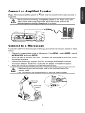
We recommend connecting an amplified speaker to Microscope. Adjust the volume down on a big screen. 1. Change the image display mode to the Audio output port. Attach the microscope adapter to the front latch hole of the camera head. - For the eyepiece, we suggest using earphones. Adjust the microscope and focus first. Press MENU > select MODE > select MICROSCOPE and press ENTER. 2. Microscope Adapter Microscope eyepiece 2.5cm 2.2cm Microscope...
We recommend connecting an amplified speaker to Microscope. Adjust the volume down on a big screen. 1. Change the image display mode to the Audio output port. Attach the microscope adapter to the front latch hole of the camera head. - For the eyepiece, we suggest using earphones. Adjust the microscope and focus first. Press MENU > select MODE > select MICROSCOPE and press ENTER. 2. Microscope Adapter Microscope eyepiece 2.5cm 2.2cm Microscope...

DCP10 User Manual
Page 16
... a USB Flash Drive Make sure to set the USB Flash Drive switch (see fig. 1.2 #1) to eject and pull the card out. To remove the card, push to the right before inserting a USB flash drive. The supported SD card capacity is connected, all captured still images will be saved in the built-in memory. ENGLISH External Memory Storage DCP10 supports both SD memory card and USB flash...
... a USB Flash Drive Make sure to set the USB Flash Drive switch (see fig. 1.2 #1) to eject and pull the card out. To remove the card, push to the right before inserting a USB flash drive. The supported SD card capacity is connected, all captured still images will be saved in the built-in memory. ENGLISH External Memory Storage DCP10 supports both SD memory card and USB flash...
DCP10 User Manual
Page 19
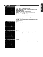
... least 55cm away from the camera. adjust the contrast along the edges making text appear more visible. adjust the gradient of image. Microscope - Macro - Effect Convert the image into original factory default setting. 17 Motion - increase frame rate. automatically adjust optical zoom for microscopic viewing. Default Restore all the settings into positive (true color), monochrome (black and white) or negative. Graphics - Focus Manually adjust the focus. Sharp - Infinite -
... least 55cm away from the camera. adjust the contrast along the edges making text appear more visible. adjust the gradient of image. Microscope - Macro - Effect Convert the image into original factory default setting. 17 Motion - increase frame rate. automatically adjust optical zoom for microscopic viewing. Default Restore all the settings into positive (true color), monochrome (black and white) or negative. Graphics - Focus Manually adjust the focus. Sharp - Infinite -
DCP10 User Manual
Page 20
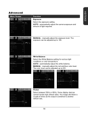
... adjusted up to 100. Some display devices cannot handle high refresh rates. manually adjust the red and blue color level. White Balance Select the White Balance setting for various light conditions or color temperature. MANUAL - The exposure can be adjusted up to another refresh rate. 18 MANUAL - Flicker Select between 50Hz or 60Hz. The image will flicker a couple of light required. automatically adjust the white balance. ENGLISH Advanced Menu Screen Function Exposure Select the exposure setting. AUTO...
... adjusted up to 100. Some display devices cannot handle high refresh rates. manually adjust the red and blue color level. White Balance Select the White Balance setting for various light conditions or color temperature. MANUAL - The exposure can be adjusted up to another refresh rate. 18 MANUAL - Flicker Select between 50Hz or 60Hz. The image will flicker a couple of light required. automatically adjust the white balance. ENGLISH Advanced Menu Screen Function Exposure Select the exposure setting. AUTO...

DCP10 User Manual
Page 25
... the selected memory. This selection will appear. ENGLISH Menu Screen Function Current Storage Change the storage location. Built-in Memory SD Memory Card USB Flash Drive Format Storage Format to stop formatting the storage. A Warning Message will be saved in TV output mode. Output Resolution Set the resolution to display the image on screen. Device Projector LCD TV RGB OUTPUT 1024X768 1280X720 1280X960 1600X1200 1920X1080 - DVI OUTPUT...
... the selected memory. This selection will appear. ENGLISH Menu Screen Function Current Storage Change the storage location. Built-in Memory SD Memory Card USB Flash Drive Format Storage Format to stop formatting the storage. A Warning Message will be saved in TV output mode. Output Resolution Set the resolution to display the image on screen. Device Projector LCD TV RGB OUTPUT 1024X768 1280X720 1280X960 1600X1200 1920X1080 - DVI OUTPUT...

DCP10 User Manual
Page 26
... hard disk. ENGLISH Menu Screen Function USB State Select the status of the DCP10 when it is set to the selected profile number. 24 Mass Storage - Backup Copy the image from the memory to SD or USB flash drive. USB Camera - Only effect, mode, brightness and contrast settings can be saved. Make sure the USB Flash Drive switch is connected to record video and capture still image. Profile Recall...
... hard disk. ENGLISH Menu Screen Function USB State Select the status of the DCP10 when it is set to the selected profile number. 24 Mass Storage - Backup Copy the image from the memory to SD or USB flash drive. USB Camera - Only effect, mode, brightness and contrast settings can be saved. Make sure the USB Flash Drive switch is connected to record video and capture still image. Profile Recall...

DCP10 User Manual
Page 28
... STORAGE before connecting the USB cable. 3. Upon connecting the USB cable, the system automatically detects the new removable disk. When "Mass Storage Start..." MUST set the USB Flash Drive switch (see fig. 1.2 #1) to the right for the computer to detect DCP10. 2. You can now transfer the captured image(s) from the built-in memory or SD to a computer. ENGLISH Menu Screen Function Current Storage Select the source of the...
... STORAGE before connecting the USB cable. 3. Upon connecting the USB cable, the system automatically detects the new removable disk. When "Mass Storage Start..." MUST set the USB Flash Drive switch (see fig. 1.2 #1) to the right for the computer to detect DCP10. 2. You can now transfer the captured image(s) from the built-in memory or SD to a computer. ENGLISH Menu Screen Function Current Storage Select the source of the...
DCP10 User Manual
Page 29
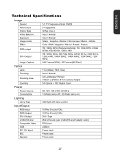
... Image Capture 240 Frames(XGA) ; 80 Frames(5M Pixel) Optics Lens F3.2 (Wide); UXGA 60 Hz; HD 720p 60Hz; F6.8 (Tele) Focusing Auto / Manual Shooting Area A4 Landscape/ Portrait 372mm x 279mm (47cm camera height) Zooming 5X Optical + 16X Digital Zoom Power Power Source DC 12V, 100-240V, 50-60Hz Consumption 18 Watts (lamp off); 20 Watts (lamp on) Lighting Lamp Type LED light with laser pointer Input/Output RGB Input...
... Image Capture 240 Frames(XGA) ; 80 Frames(5M Pixel) Optics Lens F3.2 (Wide); UXGA 60 Hz; HD 720p 60Hz; F6.8 (Tele) Focusing Auto / Manual Shooting Area A4 Landscape/ Portrait 372mm x 279mm (47cm camera height) Zooming 5X Optical + 16X Digital Zoom Power Power Source DC 12V, 100-240V, 50-60Hz Consumption 18 Watts (lamp off); 20 Watts (lamp on) Lighting Lamp Type LED light with laser pointer Input/Output RGB Input...
DCP10 User Manual
Page 30
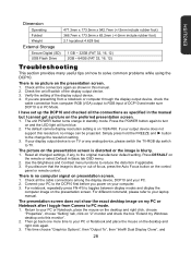
... POWER button turns orange in Basic tab OSD menu. 2. The default camera display resolution setting is on the presentation screen is distorted or the image is on TV or any , to your output device does not support this resolution; no image can be projected. The picture on 1024x768. Press DEFAULT on the remote or select Default in standby mode. Check all the cable connections among the display device, DCP10 and your PC. 2. If you power on your laptop manual...
... POWER button turns orange in Basic tab OSD menu. 2. The default camera display resolution setting is on the presentation screen is distorted or the image is on TV or any , to your output device does not support this resolution; no image can be projected. The picture on 1024x768. Press DEFAULT on the remote or select Default in standby mode. Check all the cable connections among the display device, DCP10 and your PC. 2. If you power on your laptop manual...
DCP10 Data Sheet
Page 1
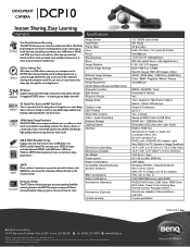
... the DCP10 with the 5-megapixel CMOS sensor - Image Sensor Total Pixels Frame Rate Lens Focus Shooting Area Zoom Image Rotation Internal Image Storage External Image Storage Image Effective Image Adjustment (White Balance/Exposure/Night View) Presenter Function Split Screen Picture-in-Picture Display Mode Capture mode User Profiles Flicker filter Control Video + Audio Recording External Storage Lighting System Interface USB & SDHC Extended Storage Capture and save more time for class! You can access this convenient feature directly on the control panel...
... the DCP10 with the 5-megapixel CMOS sensor - Image Sensor Total Pixels Frame Rate Lens Focus Shooting Area Zoom Image Rotation Internal Image Storage External Image Storage Image Effective Image Adjustment (White Balance/Exposure/Night View) Presenter Function Split Screen Picture-in-Picture Display Mode Capture mode User Profiles Flicker filter Control Video + Audio Recording External Storage Lighting System Interface USB & SDHC Extended Storage Capture and save more time for class! You can access this convenient feature directly on the control panel...


