
Wall Mount User Manual
Page 1
... ceiling. 7. The wall should be attached or hung from long term use damaged parts. Do not replace any questions. 11. Holes for any damage or injury resulting from natural causes, such as an earthquake or typhoon. 4. This projector wall mounting bracket must be installed on the wall mounting bracket. To ensure safe installation and avoid accidents, check the wall structure and select a solid durable location...
... ceiling. 7. The wall should be attached or hung from long term use damaged parts. Do not replace any questions. 11. Holes for any damage or injury resulting from natural causes, such as an earthquake or typhoon. 4. This projector wall mounting bracket must be installed on the wall mounting bracket. To ensure safe installation and avoid accidents, check the wall structure and select a solid durable location...

Wall Mount User Manual
Page 2
...E. Installing the xing bracket on the arm. 3. Assemble the hinge module (A) and the projector main support member (Q). Cable Management A. C. E. English Introduction Packaged Parts P.3 Required Tools / Torque Adjustment P.4 Angle Adjustment P.4 1. Adjust the distance between the projector and the projected image: (A) Move the projector bracket. (B) or adjust the distance of the projected image. 4. Use a hammer to enable projector horizontally lateral moves. 6. Screw the self-tapping screws (C) into the projector. Plug the power cord into the wall. Using...
...E. Installing the xing bracket on the arm. 3. Assemble the hinge module (A) and the projector main support member (Q). Cable Management A. C. E. English Introduction Packaged Parts P.3 Required Tools / Torque Adjustment P.4 Angle Adjustment P.4 1. Adjust the distance between the projector and the projected image: (A) Move the projector bracket. (B) or adjust the distance of the projected image. 4. Use a hammer to enable projector horizontally lateral moves. 6. Screw the self-tapping screws (C) into the projector. Plug the power cord into the wall. Using...
Wall Mount User Manual
Page 3
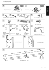
English Packaged parts A Hinge module__1pcs Connection plate A A Hinge module__1pcs Connection plate B C D E Plastic plug__6pcs Tapping screw__6pcs Hinge connector__1pcs G H Hex Head Screws(M6 xL10 )___2pcs J K L Hex bolts (M6xL25)__1pcs M F Hex bolts(M6 xL8)__4pcs I Shim Screws__4pcs N Height adjustment pipe __4pcs Hex key(5mm) __1pcs O Wrenches (10mm)___1pcs Cable management cap__1pcs P lower plastic cap__1pcs upper plastic cap__1pcs wall bracket__1pcs Q projector main pole__1pcs 3 Packaged parts
English Packaged parts A Hinge module__1pcs Connection plate A A Hinge module__1pcs Connection plate B C D E Plastic plug__6pcs Tapping screw__6pcs Hinge connector__1pcs G H Hex Head Screws(M6 xL10 )___2pcs J K L Hex bolts (M6xL25)__1pcs M F Hex bolts(M6 xL8)__4pcs I Shim Screws__4pcs N Height adjustment pipe __4pcs Hex key(5mm) __1pcs O Wrenches (10mm)___1pcs Cable management cap__1pcs P lower plastic cap__1pcs upper plastic cap__1pcs wall bracket__1pcs Q projector main pole__1pcs 3 Packaged parts
Wall Mount User Manual
Page 4
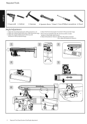
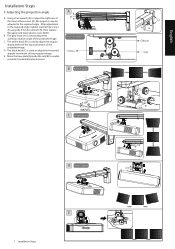
... rotation angle of the sides of the projector to enable 3. Adjust the mounting bracket arm of the projected image. 5.Move the base plate(A)inside the rails the rails (B) to ±5°. 4. the bottom of the projected image. 2. Drill bit 3. Pencil Angle Adjustment 1. Power drill 2. Adjust the horizontal angular movement of the projected image. 6. Adjust the projection distance: (A) Move the projector bracket. (B) or adjust the projection distance. 1 2 3 4 5 6 A B 4 Required Tools/Speci cations/Size...
... rotation angle of the sides of the projector to enable 3. Adjust the mounting bracket arm of the projected image. 5.Move the base plate(A)inside the rails the rails (B) to ±5°. 4. the bottom of the projected image. 2. Drill bit 3. Pencil Angle Adjustment 1. Power drill 2. Adjust the horizontal angular movement of the projected image. 6. Adjust the projection distance: (A) Move the projector bracket. (B) or adjust the projection distance. 1 2 3 4 5 6 A B 4 Required Tools/Speci cations/Size...
Wall Mount User Manual
Page 5
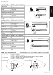
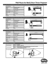
English Speci cations 215mm 215mm Ultra Short Throw Wall Mount (5J.J3A10.021) Connection plate A Material Steel/Aluminum alloy Weight 3.6 kg (7.93 lbs) Size (W x H x L) 110 x 215 x 558mm Maximum distance from wall 460mm Rotation angle +/-10˚ Load 15kg (33.07bs) Screw M4 Tilt angle +/-10° Ultra Short Throw Wall Mount (5J.J4V10.011) Connection plate A Material Steel/Aluminum alloy Weight 4.02...
English Speci cations 215mm 215mm Ultra Short Throw Wall Mount (5J.J3A10.021) Connection plate A Material Steel/Aluminum alloy Weight 3.6 kg (7.93 lbs) Size (W x H x L) 110 x 215 x 558mm Maximum distance from wall 460mm Rotation angle +/-10˚ Load 15kg (33.07bs) Screw M4 Tilt angle +/-10° Ultra Short Throw Wall Mount (5J.J4V10.011) Connection plate A Material Steel/Aluminum alloy Weight 4.02...
Wall Mount User Manual
Page 6
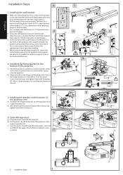
... (A) and the projector main support member (Q). Plug the power cord into the holes. B B. Install the projector bracket (A) on the bottom of the projector main support member (Q) and the wall bracket (P) by using shim screws (I 0.5mm E G K E F H L B Q L BM N O O 6 Installation Steps 4. B. the horizontal direction. J B. C. Hold the bracket (P) rmly against the wall and mark the places for a P masonry wall should be in diameter and 55mm deep (2.17"). Cable Management...
... (A) and the projector main support member (Q). Plug the power cord into the holes. B B. Install the projector bracket (A) on the bottom of the projector main support member (Q) and the wall bracket (P) by using shim screws (I 0.5mm E G K E F H L B Q L BM N O O 6 Installation Steps 4. B. the horizontal direction. J B. C. Hold the bracket (P) rmly against the wall and mark the places for a P masonry wall should be in diameter and 55mm deep (2.17"). Cable Management...
Wall Mount User Manual
Page 7
C. A Knob color indication Yellow B Knob A (gray) C Knob B (yellow) F H Black Gray D Knob C (black) E 7 Installation Steps A B Using a hex wrench (K) to adjust the sideways rotation angle of the projected image. E. The yellow knob (B) is used to adjust the tightness of the projected image. The gray knob (A) is used to adjust the horizontal angular movement of the internal hex screws (H), the projector may be adjusted to adjust the angular displacement of the top and bottom of...
C. A Knob color indication Yellow B Knob A (gray) C Knob B (yellow) F H Black Gray D Knob C (black) E 7 Installation Steps A B Using a hex wrench (K) to adjust the sideways rotation angle of the projected image. E. The yellow knob (B) is used to adjust the tightness of the projected image. The gray knob (A) is used to adjust the horizontal angular movement of the internal hex screws (H), the projector may be adjusted to adjust the angular displacement of the top and bottom of...
Wall Mount Data Sheet
Page 1
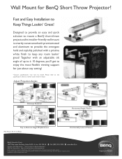
... trademarks featured or referred to review each model in this installer-friendly wall mount is smartly constructed with premium steel and aluminum to enjoy the most flexible viewing support for BenQ Short Throw Projector! Please refer to the specification chart to in detail. All rights reserved. Fast and Easy Installation to keep any setting! *Custom specifications may vary by model. Wall Mount for just about any room...
... trademarks featured or referred to review each model in this installer-friendly wall mount is smartly constructed with premium steel and aluminum to enjoy the most flexible viewing support for BenQ Short Throw Projector! Please refer to the specification chart to in detail. All rights reserved. Fast and Easy Installation to keep any setting! *Custom specifications may vary by model. Wall Mount for just about any room...
Wall Mount Data Sheet
Page 2
Wall Mount for BenQ Short Throw Projector EnEgnElignslhgislhish 215 ...Connection plate B Mark CBA ==> MMPWP778781204SSSTTT//MLXPW678076S60STUT/LSW/TMi6/MP1S7P8T72/8MS0TXS/8TM1+5XS8T1/0MSXT8/1M6WST811ST/ MX812ST / MX813ST Connection plate B Mark CB ====>> MMWP788104SSTT//MLXW6806S0TU/LSWTi6/M1SPT7/8M0XS8T1+5ST/MX816ST Connection plate A Mark C ==> MP780ST/MW860USTi/MPC7o8n0nSeTct+ion plate B Connection plate A Connection plate B Connection plate A Connection plate B Lens Direction LLeennss DDiirreeccttiioonn Lens Direction Lens Direction LLeennss DDiirreeccttiioonn Lens...
Wall Mount for BenQ Short Throw Projector EnEgnElignslhgislhish 215 ...Connection plate B Mark CBA ==> MMPWP778781204SSSTTT//MLXPW678076S60STUT/LSW/TMi6/MP1S7P8T72/8MS0TXS/8TM1+5XS8T1/0MSXT8/1M6WST811ST/ MX812ST / MX813ST Connection plate B Mark CB ====>> MMWP788104SSTT//MLXW6806S0TU/LSWTi6/M1SPT7/8M0XS8T1+5ST/MX816ST Connection plate A Mark C ==> MP780ST/MW860USTi/MPC7o8n0nSeTct+ion plate B Connection plate A Connection plate B Connection plate A Connection plate B Lens Direction LLeennss DDiirreeccttiioonn Lens Direction Lens Direction LLeennss DDiirreeccttiioonn Lens...


