
Wall Mount User Manual
Page 1
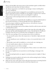
... strength to vibration or shock. • Keep the projector out of the mounting location before installation and retain them for any parts or use . 2 Warning It should be installed by service professionals. 5. The wall mounting bracket is not liable for the installation or removal of this installation guide carefully before installation. • Do not install in places where the temperature or humidity is high and avoid moisture. • Do not...
... strength to vibration or shock. • Keep the projector out of the mounting location before installation and retain them for any parts or use . 2 Warning It should be installed by service professionals. 5. The wall mounting bracket is not liable for the installation or removal of this installation guide carefully before installation. • Do not install in places where the temperature or humidity is high and avoid moisture. • Do not...
Wall Mount User Manual
Page 2
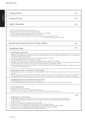
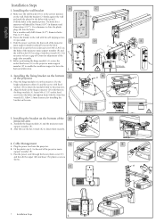
.... 2. B. Installing the bracket on the wall. Plug the power cord into the front of the projected image. 4. B. Specifications/Size/Guide sheet for adjusting the angular displacement of the top and bottom of the projected image. 5. E. Use the height adjustment collars (I) and screws with fixed washers (H) to fasten it out at the marked points. Align the hinge connector (D) with a pencil. Assembling the hinge module (A) and projector main support (P). B. The...
.... 2. B. Installing the bracket on the wall. Plug the power cord into the front of the projected image. 4. B. Specifications/Size/Guide sheet for adjusting the angular displacement of the top and bottom of the projected image. 5. E. Use the height adjustment collars (I) and screws with fixed washers (H) to fasten it out at the marked points. Align the hinge connector (D) with a pencil. Assembling the hinge module (A) and projector main support (P). B. The...
Wall Mount User Manual
Page 3
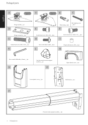
English Packaged parts A Connection A Connection B C plate A plate B Hinge module__1pc D Hinge connector__1pc G Socket head screw (M6 x L25)__1pc K Plastic plug__6pcs Self-tapping screw __6pcs E F Socket head screw (M6 x L8)__4pcs H Socket head screw (M6 x L12)__2pcs I Screw with fixed washer__4pcs L Height adjustment collar__4pcs M Hex wrench (Allen Key) (5mm)__1pc N Cap for projector main support member__1pc O Upper plastic cover__1pc Lower plastic cover__1pc P Wall bracket__1pc 4 Packaged parts Projector main support member__1pc
English Packaged parts A Connection A Connection B C plate A plate B Hinge module__1pc D Hinge connector__1pc G Socket head screw (M6 x L25)__1pc K Plastic plug__6pcs Self-tapping screw __6pcs E F Socket head screw (M6 x L8)__4pcs H Socket head screw (M6 x L12)__2pcs I Screw with fixed washer__4pcs L Height adjustment collar__4pcs M Hex wrench (Allen Key) (5mm)__1pc N Cap for projector main support member__1pc O Upper plastic cover__1pc Lower plastic cover__1pc P Wall bracket__1pc 4 Packaged parts Projector main support member__1pc
Wall Mount User Manual
Page 4
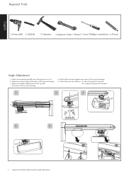
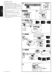
Power drill 2. Hammer 4. Pencil English Angle Adjustment 1. Adjust the rotation angle of the sides of the projector to ±5°. 2. Adjust the projection distance: (A) Move the projector bracket. (B) or adjust the projection distance. 1 2 3 4 5 5 Required Tools/Specifications/Size/Angle adjustment B A Adjust the mounting brack+e-t arm of the projected image. 3. Drill bit 3. Adjust the horizontal angular movement of the projected image. 4. Cross (Phillips) screwdriver 6. Adjust the angular displacement of the top and the bottom of the...
Power drill 2. Hammer 4. Pencil English Angle Adjustment 1. Adjust the rotation angle of the sides of the projector to ±5°. 2. Adjust the projection distance: (A) Move the projector bracket. (B) or adjust the projection distance. 1 2 3 4 5 5 Required Tools/Specifications/Size/Angle adjustment B A Adjust the mounting brack+e-t arm of the projected image. 3. Drill bit 3. Adjust the horizontal angular movement of the projected image. 4. Cross (Phillips) screwdriver 6. Adjust the angular displacement of the top and the bottom of the...
Wall Mount User Manual
Page 5
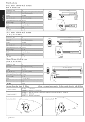
English Specifications Ultra Short Throw Wall Mount P/N 5J.J3A10.001 215mm Connection plate A Material Steel/Aluminum alloy Weight Kg (lbs) Size (W x H x L) 110 x 215 x 558mm Maximum distance from wall 462mm Rotation angle +/-10˚ Load 12kg (26.46lbs) Screw Tilt angle M4 +/-10° Ultra Short Throw Wall Mount (P/N 5J.J4V10.001) Connection plate A Material Steel/Aluminum alloy Weight Kg (lbs) Size (W x H x L) 110 x 215 x 803mm...
English Specifications Ultra Short Throw Wall Mount P/N 5J.J3A10.001 215mm Connection plate A Material Steel/Aluminum alloy Weight Kg (lbs) Size (W x H x L) 110 x 215 x 558mm Maximum distance from wall 462mm Rotation angle +/-10˚ Load 12kg (26.46lbs) Screw Tilt angle M4 +/-10° Ultra Short Throw Wall Mount (P/N 5J.J4V10.001) Connection plate A Material Steel/Aluminum alloy Weight Kg (lbs) Size (W x H x L) 110 x 215 x 803mm...
Wall Mount User Manual
Page 6
... adjustment of the projector main support member (P) and the wall bracket (O) by using a 5mm hex wrench (K). It is in the horizontal direction. 1. 2. Place the hinge module (A) on the wall. Cable Management A A. Pass the power cord through the lower plastic cover (N) and then fit the upper (M) and lower (N) plastic covers as shown. B. Assemble the hinge module (A) and the projector main support member (P). Plug the power cord...
... adjustment of the projector main support member (P) and the wall bracket (O) by using a 5mm hex wrench (K). It is in the horizontal direction. 1. 2. Place the hinge module (A) on the wall. Cable Management A A. Pass the power cord through the lower plastic cover (N) and then fit the upper (M) and lower (N) plastic covers as shown. B. Assemble the hinge module (A) and the projector main support member (P). Plug the power cord...
Wall Mount User Manual
Page 7
... projected image. C. English Installation Steps 5. By adjusting the tightness of the socket head screw (G) using a 5mm hex wrench (K), then replace the upper and lower plastic caps (M)(N). D. B. The yellow knob (B) is used to push back and tighten the knobs securely after making any adjustment. Be sure to adjust the sideways rotation angle of the projected image. A Knob color indication G B Gray Black Yellow C Knob A (gray) D Knob B (yellow) E Knob C (black) F 8 Installation Steps Adjusting...
... projected image. C. English Installation Steps 5. By adjusting the tightness of the socket head screw (G) using a 5mm hex wrench (K), then replace the upper and lower plastic caps (M)(N). D. B. The yellow knob (B) is used to push back and tighten the knobs securely after making any adjustment. Be sure to adjust the sideways rotation angle of the projected image. A Knob color indication G B Gray Black Yellow C Knob A (gray) D Knob B (yellow) E Knob C (black) F 8 Installation Steps Adjusting...
Wall Mount Data Sheet
Page 1
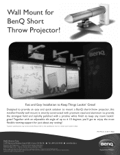
... - Together with a pristine white finish to enjoy the most flexible viewing support for BenQ Short Throw Projector! http://promotions.benq.us/dealregistration/ BenQ is a registered trademark of up to ± 10 degrees, you'll get to keep any setting! *Custom specifications may vary by model. Please refer to the specification chart to in detail. Wall Mount 12-20-11-BQus BenQ America Corp. 15375 Barranca...
... - Together with a pristine white finish to enjoy the most flexible viewing support for BenQ Short Throw Projector! http://promotions.benq.us/dealregistration/ BenQ is a registered trademark of up to ± 10 degrees, you'll get to keep any setting! *Custom specifications may vary by model. Please refer to the specification chart to in detail. Wall Mount 12-20-11-BQus BenQ America Corp. 15375 Barranca...
Wall Mount Data Sheet
Page 2
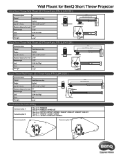
Wall Mount for BenQ Short Throw Projector UltraUShltorartSThhorrotwTWhroalwl MWouanlltM(0o.u3nTth(r0o.3wTRhartoiow, PR/Nati5oJ,.JP3/AN105.J0.J031A)10.001) 8.46" Connection plate A Material Steel/Aluminum alloy Weight Kg (lbs) Size (W x H x L) 4.33" x 8.46" x 21.97" Maximum distance from wall 18.19" Rotation angle +/-10˚ Load 26.46 lbs (12kg) Screw Tilt angle M4 +/-10° 4.33" 11.46" 7.36...
Wall Mount for BenQ Short Throw Projector UltraUShltorartSThhorrotwTWhroalwl MWouanlltM(0o.u3nTth(r0o.3wTRhartoiow, PR/Nati5oJ,.JP3/AN105.J0.J031A)10.001) 8.46" Connection plate A Material Steel/Aluminum alloy Weight Kg (lbs) Size (W x H x L) 4.33" x 8.46" x 21.97" Maximum distance from wall 18.19" Rotation angle +/-10˚ Load 26.46 lbs (12kg) Screw Tilt angle M4 +/-10° 4.33" 11.46" 7.36...


