Installation Manual
Page 2
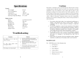
Specifications General Power Supply Power Consumption Current Draw Audio Power Output Operating Temperature Range DC12V
Specifications General Power Supply Power Consumption Current Draw Audio Power Output Operating Temperature Range DC12V
Installation Manual
Page 3
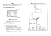
... to 3 different video inputs. INSTALLATION INSTRUCTIONS Screw holes for mounting bracket 1 T slot for Navigation Navigation Computer Connector LCD Monitor Connector Control Box Connector Connector Connector Filter Box Interior camera Rearview camera Fuse Red Black Blue Green Fused +12V Constant ... visible to the selected mounting location. 2. Then place the fan bracket on the fan bracket. System Connections 7 Preface This video monitor can be mounted by two different methods. • AMPS compatible mounting pattern for bracket or gooseneck • T-slot for Fan Bracket. ...
... to 3 different video inputs. INSTALLATION INSTRUCTIONS Screw holes for mounting bracket 1 T slot for Navigation Navigation Computer Connector LCD Monitor Connector Control Box Connector Connector Connector Filter Box Interior camera Rearview camera Fuse Red Black Blue Green Fused +12V Constant ... visible to the selected mounting location. 2. Then place the fan bracket on the fan bracket. System Connections 7 Preface This video monitor can be mounted by two different methods. • AMPS compatible mounting pattern for bracket or gooseneck • T-slot for Fan Bracket. ...
Installation Manual
Page 4
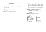
... • Power harness: Connect the power 4-pin connector to the control box 8-pin female connector. System Connections 6 3 Connect the 8-pin male monitor extension cable connector to the control box 4-pin connector. Chassis ground (negative) c) Blue wire - 12-volt ignition (12 volt with ignition on...vehicle is in the harness as listed below . 4. Control BOX To Control BOX Cam Button Selector Switch To Rearview Camera To Interior Camera To LCD monitor To Filter BOX Filter BOX Red (+12V) Blue (Ignition) Black (GND) Green (Reverse) Figure 2. Attach the 4 wires in the ...
... • Power harness: Connect the power 4-pin connector to the control box 8-pin female connector. System Connections 6 3 Connect the 8-pin male monitor extension cable connector to the control box 4-pin connector. Chassis ground (negative) c) Blue wire - 12-volt ignition (12 volt with ignition on...vehicle is in the harness as listed below . 4. Control BOX To Control BOX Cam Button Selector Switch To Rearview Camera To Interior Camera To LCD monitor To Filter BOX Filter BOX Red (+12V) Blue (Ignition) Black (GND) Green (Reverse) Figure 2. Attach the 4 wires in the ...
Installation Manual
Page 5
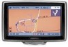
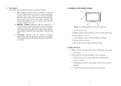
...the AV-2 position. b) Interior Camera (optional): Plug the camera RJ 11 cable end into camera 4 pin female connector. LCM45NB Monitor Controls and Indicators A: 4.5" TFT color LCD B: Speaker volume control: adjusts the rearview camera volume only when the vehicle is in any other gear: • Will... shifted into the rear of display. When switch D is pressed and the vehicle is pressed and held c) Navigation (optional): Plug the Audiovox navigation monitor cable connector directly into reverse gear: • No function 2). When switch D is pressed and vehicle is the only input. 5 ...
...the AV-2 position. b) Interior Camera (optional): Plug the camera RJ 11 cable end into camera 4 pin female connector. LCM45NB Monitor Controls and Indicators A: 4.5" TFT color LCD B: Speaker volume control: adjusts the rearview camera volume only when the vehicle is in any other gear: • Will... shifted into the rear of display. When switch D is pressed and the vehicle is pressed and held c) Navigation (optional): Plug the Audiovox navigation monitor cable connector directly into reverse gear: • No function 2). When switch D is pressed and vehicle is the only input. 5 ...


