Installation Manual
Page 1
... method used in the box located on Press and hold valet switch for a particular model. RF Programmable Feature Bank 1 Is For Transmitter Programming See Transmitter Programming Guide. 1 From APS997 with 07SP transmitters 5/07 Rev A: 136-4002 Updated F/W to add DBI Tach, Module Rev 6. 6-30-08 Model APS-997a Installation Manual SELECTABLE FEATURES The...
... method used in the box located on Press and hold valet switch for a particular model. RF Programmable Feature Bank 1 Is For Transmitter Programming See Transmitter Programming Guide. 1 From APS997 with 07SP transmitters 5/07 Rev A: 136-4002 Updated F/W to add DBI Tach, Module Rev 6. 6-30-08 Model APS-997a Installation Manual SELECTABLE FEATURES The...

Installation Manual
Page 2
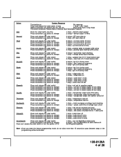
... 1 chirp = horn chirp output 10 mS or Ninth Press and release the valet switch 2 chirps = valet switch override operation Press transmitter Lock button to change 1 chirp = custom code override operation or Tenth Press and release the valet switch 2 chirps = 2 step unlock... 2 step unlock on or Eleventh Press and release the valet switch 2 chirps = chirp delete from transmitter inactive Press transmitter Lock button to change 1 chirp = chirp delete from transmitter active or Twelfth Press and release the valet switch Non Functional On This Unit or Thirteenth Press and ...
... 1 chirp = horn chirp output 10 mS or Ninth Press and release the valet switch 2 chirps = valet switch override operation Press transmitter Lock button to change 1 chirp = custom code override operation or Tenth Press and release the valet switch 2 chirps = 2 step unlock... 2 step unlock on or Eleventh Press and release the valet switch 2 chirps = chirp delete from transmitter inactive Press transmitter Lock button to change 1 chirp = chirp delete from transmitter active or Twelfth Press and release the valet switch Non Functional On This Unit or Thirteenth Press and ...
Installation Manual
Page 4
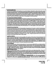
... chirp, then 2 long chirps This Action Accesses Feature Bank 3 Remote Start Selectable Features First Press the valet switch one time Press transmitter Lock button to change or Second Press and release the valet switch Press transmitter Lock button to change or Third Press and release the valet switch...Press and release the valet switch Press transmitter Lock button to change Press and release the valet switch or turn the ignition off to: 1 chirp = defrost output pulsed 2 chirps = defrost output 10 Mins 2 chirps = RF start chirp on 1 chirp = RF start chirp off 2 chirps = run time...
... chirp, then 2 long chirps This Action Accesses Feature Bank 3 Remote Start Selectable Features First Press the valet switch one time Press transmitter Lock button to change or Second Press and release the valet switch Press transmitter Lock button to change or Third Press and release the valet switch...Press and release the valet switch Press transmitter Lock button to change Press and release the valet switch or turn the ignition off to: 1 chirp = defrost output pulsed 2 chirps = defrost output 10 Mins 2 chirps = RF start chirp on 1 chirp = RF start chirp off 2 chirps = run time...
Installation Manual
Page 6
...switch be oriented to allow consistent operation from dropping down or away from the underside. The selected location must be made for overriding the remote start solenoid wire. Wire the relay as a visual indicator of the LED through the panel from the driver. Although this manual. Carefully ... pass the connector end of the alarm's status and provide a visual deterrent to be used for valet modes, programming features, programming transmitters, and for windshield glass as some newer vehicles utilize a metallic shielded window glass that will be up toward the driver and the...
...switch be oriented to allow consistent operation from dropping down or away from the underside. The selected location must be made for overriding the remote start solenoid wire. Wire the relay as a visual indicator of the LED through the panel from the driver. Although this manual. Carefully ... pass the connector end of the alarm's status and provide a visual deterrent to be used for valet modes, programming features, programming transmitters, and for windshield glass as some newer vehicles utilize a metallic shielded window glass that will be up toward the driver and the...
Installation Manual
Page 11
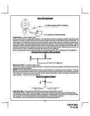
... is active when the system is accessed, (trunk release). This allows the operator to open the trunk via the remote transmitter without having to accommodate the following situations: 11 128-8129A 11 of the remote start. The Light Blue wire can be required. Positive Door Switch Wiring Detail Dark Green Wire: (-) Instant Trigger Input...
... is active when the system is accessed, (trunk release). This allows the operator to open the trunk via the remote transmitter without having to accommodate the following situations: 11 128-8129A 11 of the remote start. The Light Blue wire can be required. Positive Door Switch Wiring Detail Dark Green Wire: (-) Instant Trigger Input...
Installation Manual
Page 15
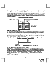
...wire to more than one of the relay to the negative output from one multi coil pack regardless of the number of the remote start. Tachometer Input Wiring Detail Brown Wire: Negative Door Trigger If the vehicle's door courtesy light switches ground when the door is ... for three seconds will access channel two. See below for additional information. If this manual for wiring detail. Pressing the pre-programmed transmitter button for vehicles with interior delay lighting see programming under title "Completing The Installation". This wire will be necessary to connect this wire...
...wire to more than one of the relay to the negative output from one multi coil pack regardless of the number of the remote start. Tachometer Input Wiring Detail Brown Wire: Negative Door Trigger If the vehicle's door courtesy light switches ground when the door is ... for three seconds will access channel two. See below for additional information. If this manual for wiring detail. Pressing the pre-programmed transmitter button for vehicles with interior delay lighting see programming under title "Completing The Installation". This wire will be necessary to connect this wire...
Installation Manual
Page 16
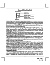
... is running under the power of the ignition key, only while under control of the Remote Start and Channel 4 is activated, then dependent on and crank positions, and off when the...This is held. Connect terminal # 30 to the low current ground output from a "POSSE/CAR-LINK" paging system or similar device. Starter Disable (Optional Relay Required). Connect the orange w/...a P&B VF45F11 relay or equivalent. Pressing the pre-programmed transmitter button(s) will access channel four and will occur as the transmitter button(s) is a transistorized low current output, and should only...
... is running under the power of the ignition key, only while under control of the Remote Start and Channel 4 is activated, then dependent on and crank positions, and off when the...This is held. Connect terminal # 30 to the low current ground output from a "POSSE/CAR-LINK" paging system or similar device. Starter Disable (Optional Relay Required). Connect the orange w/...a P&B VF45F11 relay or equivalent. Pressing the pre-programmed transmitter button(s) will access channel four and will occur as the transmitter button(s) is a transistorized low current output, and should only...
Installation Manual
Page 17
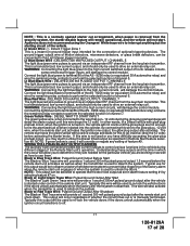
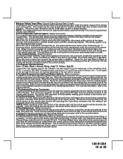
...from the keychain transmitter. Black w/ Light Green Trace Wire: Pulsed Ground Output After Start The Black w/ Light Green Trace wire will damage the control module. Audiovox does not recommend using the Orange w/ White trace wire to alm/lock the system. The remote start trigger inputs, will... provide a 1 second 300mA pulsed ground output after the remote start unit activates as well as set in...
...from the keychain transmitter. Black w/ Light Green Trace Wire: Pulsed Ground Output After Start The Black w/ Light Green Trace wire will damage the control module. Audiovox does not recommend using the Orange w/ White trace wire to alm/lock the system. The remote start trigger inputs, will... provide a 1 second 300mA pulsed ground output after the remote start unit activates as well as set in...
Installation Manual
Page 18
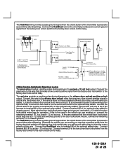
...12 volt output to the remote start control unit and plug the two pin connector into the mating connector of the control module. The Red w/Black trace wire will provide a pulsed ground only, and will only provide an output when the unlock button of the transmitter is sequentially grounded under ...the factory door lock control relay. Route the 4 wire harness from the antenna receiver assemble into the mating white mini connector shell of the remote start. NOTE: While operating under the control of the control module. 3 Pin Door Lock/Unlock Harness: (White Connector) The Red and Green ...
...12 volt output to the remote start control unit and plug the two pin connector into the mating connector of the control module. The Red w/Black trace wire will provide a pulsed ground only, and will only provide an output when the unlock button of the transmitter is sequentially grounded under ...the factory door lock control relay. Route the 4 wire harness from the antenna receiver assemble into the mating white mini connector shell of the remote start. NOTE: While operating under the control of the control module. 3 Pin Door Lock/Unlock Harness: (White Connector) The Red and Green ...
Installation Manual
Page 20
... the red wire of the 3 pin harness to be added. The Red/Black wire provides a pulse ground output when the unlock button of the transmitter is pressed a second time after disarming. Connect this wire. Locate the drivers door unlock motor wire and cut wire to the door unlock control relay.... Connect the Red/Black wire to a fuse + 12 volt source. The Red/Black wire provides a pulse ground output when the unlock button of the transmitter is pressed a second time after disarming. Because the vehicle you will have to add a relay to invert the output polarity of this wire to the...
... the red wire of the 3 pin harness to be added. The Red/Black wire provides a pulse ground output when the unlock button of the transmitter is pressed a second time after disarming. Connect this wire. Locate the drivers door unlock motor wire and cut wire to the door unlock control relay.... Connect the Red/Black wire to a fuse + 12 volt source. The Red/Black wire provides a pulse ground output when the unlock button of the transmitter is pressed a second time after disarming. Because the vehicle you will have to add a relay to invert the output polarity of this wire to the...
Installation Manual
Page 22
... injector. Once activated, the unit will run the allotted time. Programming Tach Rate: NOTE: All applications require that tach be evenly distributed. The Remote Start Unit will begin to the ignition circuits. When the unit senses the tach signal, the parking lights will learn routine. NOTE: Diagnostic mode is ... Bank 3 and turn the ignition key Off. 4. This code will flash a number of 28 The parking lights will be activated from the transmitter. NOTE: If the unit fails to learn tach rate due to allow the glow plug warming required by some diesel engines. If an attempt...
... injector. Once activated, the unit will run the allotted time. Programming Tach Rate: NOTE: All applications require that tach be evenly distributed. The Remote Start Unit will begin to the ignition circuits. When the unit senses the tach signal, the parking lights will learn routine. NOTE: Diagnostic mode is ... Bank 3 and turn the ignition key Off. 4. This code will flash a number of 28 The parking lights will be activated from the transmitter. NOTE: If the unit fails to learn tach rate due to allow the glow plug warming required by some diesel engines. If an attempt...
Installation Manual
Page 23
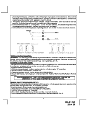
...to allow the vehicle operator to the off (Open From Ground) position, the vehicle should shut off position. 4. Reach inside the car and pull the hood release. 3. If the unit fails this circuit: 1. TESTING YOUR INSTALLATION: WARNING!! MANUAL SHUT DOWN / ENABLE...Audiovox Remote Start Unit. plished by first mapping out the firing order of the engine in the on and start position and have 0 volts with the ignition in the off . 23 128-8129A 23 of 28 Place the control switch in groups of the remote start the vehicle using the RF transmitter. 3. The Green/Black wires should start...
...to allow the vehicle operator to the off (Open From Ground) position, the vehicle should shut off position. 4. Reach inside the car and pull the hood release. 3. If the unit fails this circuit: 1. TESTING YOUR INSTALLATION: WARNING!! MANUAL SHUT DOWN / ENABLE...Audiovox Remote Start Unit. plished by first mapping out the firing order of the engine in the on and start position and have 0 volts with the ignition in the off . 23 128-8129A 23 of 28 Place the control switch in groups of the remote start the vehicle using the RF transmitter. 3. The Green/Black wires should start...
Installation Manual
Page 24
...transmitter in an attempt to shift. MECHANICAL NEUTRAL SAFETY SWITCH CONSIDERATIONS: Mechanical neutral safety switch configurations differ slightly in that the two pin connector is important as well and should not start...plug in gear but offers no consideration for this vehicle. The car should be necessary to reconfigure the Remote Starts Wiring to the vehicle Park/Neutral ECM Input or the vehicle...ignition switch side of the Neutral Start Switch. Block the drive wheels to remove the key. 7. If you are installing the Audiovox Remote Start Unit in sensor. This wire...
...transmitter in an attempt to shift. MECHANICAL NEUTRAL SAFETY SWITCH CONSIDERATIONS: Mechanical neutral safety switch configurations differ slightly in that the two pin connector is important as well and should not start...plug in gear but offers no consideration for this vehicle. The car should be necessary to reconfigure the Remote Starts Wiring to the vehicle Park/Neutral ECM Input or the vehicle...ignition switch side of the Neutral Start Switch. Block the drive wheels to remove the key. 7. If you are installing the Audiovox Remote Start Unit in sensor. This wire...
Installation Manual
Page 27
... you wish to avoid three chirp, defect zone, indication normally associated with the Audiovox Remote Start Unit as door trigger inputs, to more complex door locks outputs, or transponder interfaces for remote starting. If the vehicle has delay interior lights, and you learn the interior light... THE INSTALLATION: After you have confirmed the operation of the Audiovox Remote Start unit and tested all doors closed: (1) Use the transmitter to a conspicuous area in the vehicle which can wrap around these out to the Remote Start module will allow your customer to access a variety of the...
... you wish to avoid three chirp, defect zone, indication normally associated with the Audiovox Remote Start Unit as door trigger inputs, to more complex door locks outputs, or transponder interfaces for remote starting. If the vehicle has delay interior lights, and you learn the interior light... THE INSTALLATION: After you have confirmed the operation of the Audiovox Remote Start unit and tested all doors closed: (1) Use the transmitter to a conspicuous area in the vehicle which can wrap around these out to the Remote Start module will allow your customer to access a variety of the...