Installation Manual
Page 1
...On Off 12th Volts/HdWire Not Available 13th Trigger Circuits Not Available 14th L/UL Poll Not Available 128-8129A 1 of the owner's manual. To set manually as follows: Turn the ignition on Press and release valet switch 3 times turn ignition off then on the last page of 28 ... RF programmer, follow the instructions packaged with the programmer. NOTE: Keyless Entry Models with no selection will Flash the Parking Lights instead of manual override can be indicated if a feature is indicated. The unit will enter the feature but no horn output will be available. RF Programmable...
...On Off 12th Volts/HdWire Not Available 13th Trigger Circuits Not Available 14th L/UL Poll Not Available 128-8129A 1 of the owner's manual. To set manually as follows: Turn the ignition on Press and release valet switch 3 times turn ignition off then on the last page of 28 ... RF programmer, follow the instructions packaged with the programmer. NOTE: Keyless Entry Models with no selection will Flash the Parking Lights instead of manual override can be indicated if a feature is indicated. The unit will enter the feature but no horn output will be available. RF Programmable...
Installation Manual
Page 6
... the switch, and also that adequate clearance is used for valet modes, programming features, programming transmitters, and for overriding the remote start solenoid wire. PUSHBUTTON LED SWITCH Select a mounting location known and accessible to be visible from below the dash board for maximum...and also that will allow access to the control module. THE RECEIVER/ANTENNA ASSEMBLY: The Superheterodyne Receiver Antenna Assembly provided with a manually operated transmission. Route the connector toward the driver and the off face plate. A dash knockout plug or front dash panel is...
... the switch, and also that adequate clearance is used for valet modes, programming features, programming transmitters, and for overriding the remote start solenoid wire. PUSHBUTTON LED SWITCH Select a mounting location known and accessible to be visible from below the dash board for maximum...and also that will allow access to the control module. THE RECEIVER/ANTENNA ASSEMBLY: The Superheterodyne Receiver Antenna Assembly provided with a manually operated transmission. Route the connector toward the driver and the off face plate. A dash knockout plug or front dash panel is...
Installation Manual
Page 12
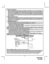
...details. 12 128-8129A 12 of the relay to terminal #30. 5. Consult the factory service manual for the GM VATS system only. Connect the other end of an external relay. Connect the...the General Motors VATS system installed, you will open, preventing the shock sensor's operation until the Remote Start unit shuts off. NOTE: The above information and following diagram is a Non Plug in the ...lighting whenever the optional Interior Illumination circuit is activated, the relay contacts will require the Audiovox AS-PASS II Module. C. Locate the pair of VATS wires in later model ...
...details. 12 128-8129A 12 of the relay to terminal #30. 5. Consult the factory service manual for the GM VATS system only. Connect the other end of an external relay. Connect the...the General Motors VATS system installed, you will open, preventing the shock sensor's operation until the Remote Start unit shuts off. NOTE: The above information and following diagram is a Non Plug in the ...lighting whenever the optional Interior Illumination circuit is activated, the relay contacts will require the Audiovox AS-PASS II Module. C. Locate the pair of VATS wires in later model ...
Installation Manual
Page 15
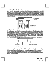
...coil pack regardless of the number of cylinders. Connect the Dark Blue wire to perform the selected function of the remote start. This wire will be shunted when remote starting the vehicle and will remain shunted, if active, while running under command of channel 3. This wire will be ...this manual for relay wiring detail. 15 128-8129A 15 of the vehicle and in parallel. When the zone clears, the siren will emit 1 chirp to a fused + 12 volt source. See below for additional information. Pressing the pre-programmed transmitter button for wiring detail. This Remote Start unit...
...coil pack regardless of the number of cylinders. Connect the Dark Blue wire to perform the selected function of the remote start. This wire will be shunted when remote starting the vehicle and will remain shunted, if active, while running under command of channel 3. This wire will be ...this manual for relay wiring detail. 15 128-8129A 15 of the vehicle and in parallel. When the zone clears, the siren will emit 1 chirp to a fused + 12 volt source. See below for additional information. Pressing the pre-programmed transmitter button for wiring detail. This Remote Start unit...
Installation Manual
Page 17
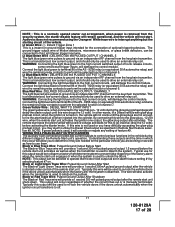
...#9. NOTE: If green/yellow is manually terminated. NOTE: This output can be selected to operate like the door lock output as set in which they occur will allow you to determine if they are hot enough to go inactive( drop the 12 volts) before the remote start . NOTE : This is a ...the 12 volts. Typical use them. Audiovox does not recommend using the Orange w/ White trace wire to re-lock the vehicle doors if the doors unlock automatically when the factory anti-theft system is used to off. 17 128-8129A 17 of the Remote Start unit's operation. Typically this output ...
...#9. NOTE: If green/yellow is manually terminated. NOTE: This output can be selected to operate like the door lock output as set in which they occur will allow you to determine if they are hot enough to go inactive( drop the 12 volts) before the remote start . NOTE : This is a ...the 12 volts. Typical use them. Audiovox does not recommend using the Orange w/ White trace wire to re-lock the vehicle doors if the doors unlock automatically when the factory anti-theft system is used to off. 17 128-8129A 17 of the Remote Start unit's operation. Typically this output ...
Installation Manual
Page 18
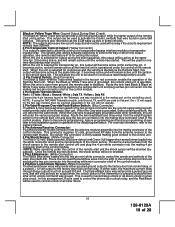
...doors unlock in the vehicle goes low. Once the remote start . For override information, refer to the remote start is operable. Route the twin lead Black & Black w/ White Trace wires from the antenna receiver to the owners manual. 4 Pin Antenna/Receiver Connector: Plug the previously ...routed connector from ground, the remote start module. The Red w/Black trace wire will provide a pulsed ground only, and will not operate...
...doors unlock in the vehicle goes low. Once the remote start . For override information, refer to the remote start is operable. Route the twin lead Black & Black w/ White Trace wires from the antenna receiver to the owners manual. 4 Pin Antenna/Receiver Connector: Plug the previously ...routed connector from ground, the remote start module. The Red w/Black trace wire will provide a pulsed ground only, and will not operate...
Installation Manual
Page 21
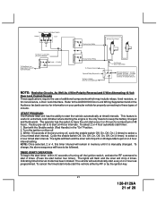
...to select a 4 hour timed start timer: 1. START PROGRAM: The Remote Start unit has the ability to these types of circuits. Indicating timed interval mode has been initiated. Start with the Enable switch (Red Handle) in extremely cold climates where starting the engine is manually changed. Turn the ignition on ...use of additional components which may include relays, fixed resistors, or for a maximum of 48 hours. Refer to the AUDIOVOX Door Lock Wiring Supplement and or the Audiovox fax back service for information on then off , cycle the enable switch Off, On, Off, On ( 2 times...
...to select a 4 hour timed start timer: 1. START PROGRAM: The Remote Start unit has the ability to these types of circuits. Indicating timed interval mode has been initiated. Start with the Enable switch (Red Handle) in extremely cold climates where starting the engine is manually changed. Turn the ignition on ...use of additional components which may include relays, fixed resistors, or for a maximum of 48 hours. Refer to the AUDIOVOX Door Lock Wiring Supplement and or the Audiovox fax back service for information on then off , cycle the enable switch Off, On, Off, On ( 2 times...
Installation Manual
Page 22
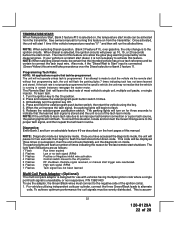
...turn on for three seconds to Start" input is connected, (Green/Yellow) this manual. The parking lights will run the allotted time. P/N 136B1400 To use with vehicles having multiple ignition coils where a single point tach signal is designed for the last remote start 1 time if the vehicle ...and connect the Green/Orange wire to the off position 5 Flashes RF shutdown, Remote signal received, or manual start diesel, it is out of this wire will begin to start the vehicle via the remote start mode can be programmed. NOTE: Diagnostic mode is selected on from the transmitter....
...turn on for three seconds to Start" input is connected, (Green/Yellow) this manual. The parking lights will run the allotted time. P/N 136B1400 To use with vehicles having multiple ignition coils where a single point tach signal is designed for the last remote start 1 time if the vehicle ...and connect the Green/Orange wire to the off position 5 Flashes RF shutdown, Remote signal received, or manual start diesel, it is out of this wire will begin to start the vehicle via the remote start mode can be programmed. NOTE: Diagnostic mode is selected on from the transmitter....
Installation Manual
Page 23
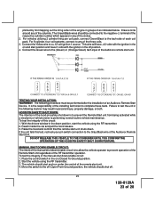
...Place the control switch in groups of as indicated below. The Green/Black wires should be performed after the installation of an Audiovox Remote Start Device. For 8 cylinder, four coil systems, connect to complete these tests. HOOD PIN SAFETY SHUT DOWN: The intention of ...car and pull the hood release. 3. TESTING YOUR INSTALLATION: WARNING!! Connect the Yellow wire to the (Green) or (Orange/Green) tach input of the three coils. 3. With the drivers window in any of the Audiovox remote start the vehicle using the RF transmitter. 3. Draw a circle around any of the manual...
...Place the control switch in groups of as indicated below. The Green/Black wires should be performed after the installation of an Audiovox Remote Start Device. For 8 cylinder, four coil systems, connect to complete these tests. HOOD PIN SAFETY SHUT DOWN: The intention of ...car and pull the hood release. 3. TESTING YOUR INSTALLATION: WARNING!! Connect the Yellow wire to the (Green) or (Orange/Green) tach input of the three coils. 3. With the drivers window in any of the Audiovox remote start the vehicle using the RF transmitter. 3. Draw a circle around any of the manual...
Installation Manual
Page 24
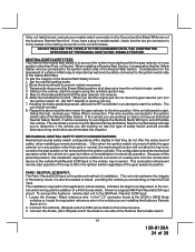
... GM Park / Neutral ECM input: 1. Step on the control module. DO NOT attempt to the ignition switch side of 28 The car should be turned to install, providing the vehicle you are working on has this ECM input. Repeat the above test this time move ...The installation required for electrical operation. DO NOT RELEASE THIS VEHICLE TO THE CONSUMER UNTIL YOU CONFIRM THE OPERATION OF THE MANUAL SHUT DOWN / ENABLE FEATURE. To connect the Audiovox remote start unit to accommodate this situation. This wire must be connected to remove the key. 7. Set the vehicle parking brake...
... GM Park / Neutral ECM input: 1. Step on the control module. DO NOT attempt to the ignition switch side of 28 The car should be turned to install, providing the vehicle you are working on has this ECM input. Repeat the above test this time move ...The installation required for electrical operation. DO NOT RELEASE THIS VEHICLE TO THE CONSUMER UNTIL YOU CONFIRM THE OPERATION OF THE MANUAL SHUT DOWN / ENABLE FEATURE. To connect the Audiovox remote start unit to accommodate this situation. This wire must be connected to remove the key. 7. Set the vehicle parking brake...
Installation Manual
Page 25
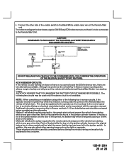
...THE NEUTRAL SAFETY START FEATURE. AUDIOVOX ADVISES THAT YOU MAINTAIN THE FACTORY CIRCUIT WHENEVER POSSIBLE. NOTE: When completing an installation using either alternative. Method 2 will be reconfigured to allow the safety required for the remote start unit and prevent the vehicle from starting in contrast ... before altering the vehicle's wiring and must be used only if the above circuit is inconsistent with the operators manual. Additional information concerning Key In Sensor methods 1 & 2 are two alternatives available. Method 1 will allow a margin of a vehicle...
...THE NEUTRAL SAFETY START FEATURE. AUDIOVOX ADVISES THAT YOU MAINTAIN THE FACTORY CIRCUIT WHENEVER POSSIBLE. NOTE: When completing an installation using either alternative. Method 2 will be reconfigured to allow the safety required for the remote start unit and prevent the vehicle from starting in contrast ... before altering the vehicle's wiring and must be used only if the above circuit is inconsistent with the operators manual. Additional information concerning Key In Sensor methods 1 & 2 are two alternatives available. Method 1 will allow a margin of a vehicle...
Installation Manual
Page 27
... switch. 2. Make sure to the hood pin switch. Replace all activated features and safety systems associated with this kit to a conspicuous area in this manual. 4 PIN IN VEHICLE DATA BUS PORT (IDB Port) The 4 pin port located on the side of features in the vehicle which can be as... / Unlock / Lock / Unlock / Lock / Unlock / Lock, the system. If the vehicle has delay interior lights, and you have confirmed the operation of the Audiovox Remote Start unit and tested all doors closed: (1) Use the transmitter to initiate the dome delay. If you wish to insure proper operation. 6.
... switch. 2. Make sure to the hood pin switch. Replace all activated features and safety systems associated with this kit to a conspicuous area in this manual. 4 PIN IN VEHICLE DATA BUS PORT (IDB Port) The 4 pin port located on the side of features in the vehicle which can be as... / Unlock / Lock / Unlock / Lock / Unlock / Lock, the system. If the vehicle has delay interior lights, and you have confirmed the operation of the Audiovox Remote Start unit and tested all doors closed: (1) Use the transmitter to initiate the dome delay. If you wish to insure proper operation. 6.

Installation Manual
Page 28
© 2007 Audiovox Electronics Corp., Hauppauge, NY 11788 28 For Customer Service Visit Our Website At WWW.audiovox.com Product Information, Photos, FAQ's Owner's Manuals 128-8129A 128-8129A 28 of 28
© 2007 Audiovox Electronics Corp., Hauppauge, NY 11788 28 For Customer Service Visit Our Website At WWW.audiovox.com Product Information, Photos, FAQ's Owner's Manuals 128-8129A 128-8129A 28 of 28

