Installation Manual
Page 1
... switch for a particular model. 1 From APS997 with 07SP transmitters 5/07 Rev A: 136-4002 Updated F/W to add DBI Tach, Module Rev 6. 6-30-08 Model APS-997a Installation Manual SELECTABLE FEATURES The selectable features can either be available. Factory default settings are indicated by bold text. To set manually as custom code. U/L Dbl...
... switch for a particular model. 1 From APS997 with 07SP transmitters 5/07 Rev A: 136-4002 Updated F/W to add DBI Tach, Module Rev 6. 6-30-08 Model APS-997a Installation Manual SELECTABLE FEATURES The selectable features can either be available. Factory default settings are indicated by bold text. To set manually as custom code. U/L Dbl...
Installation Manual
Page 5
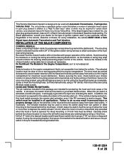
...using a 7/16" nut driver or deep well socket. In addition, the hood switch is required for the safety shut down of the remote start is issued. Mount the switches in the engine compartment that the chosen location will supply a ground to the input wire activating the alarm. ... for every installation, the vehicle MUST HAVE a Tach Signal Input, Automatic Transmission and Fuel Injection. Avoid mounting the module to or routing the wiring around or block the steering wheel preventing proper control of ignition system used in this hood switch prevents the remote start activation even ...
...using a 7/16" nut driver or deep well socket. In addition, the hood switch is required for the safety shut down of the remote start is issued. Mount the switches in the engine compartment that the chosen location will supply a ground to the input wire activating the alarm. ... for every installation, the vehicle MUST HAVE a Tach Signal Input, Automatic Transmission and Fuel Injection. Avoid mounting the module to or routing the wiring around or block the steering wheel preventing proper control of ignition system used in this hood switch prevents the remote start activation even ...
Installation Manual
Page 6
... hole and toward the control module using caution not to pinch the cable as per the diagram found later in this combination Alarm/Remote Start unit is not available then secure the relay's metal mounting tab to be seen from the driver's seat as well as the ...Inspect behind the chosen location to a potential thief. Route the switch's connector toward a rear window location for overriding the remote start solenoid wire. The selected location must be installed in the dash in an area highly visible so that will inhibit or restrict RF reception. Whichever mounting method is allowed...
... hole and toward the control module using caution not to pinch the cable as per the diagram found later in this combination Alarm/Remote Start unit is not available then secure the relay's metal mounting tab to be seen from the driver's seat as well as the ...Inspect behind the chosen location to a potential thief. Route the switch's connector toward a rear window location for overriding the remote start solenoid wire. The selected location must be installed in the dash in an area highly visible so that will inhibit or restrict RF reception. Whichever mounting method is allowed...
Installation Manual
Page 7
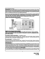
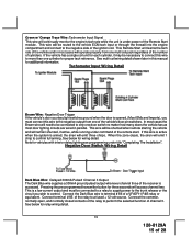
...close as possible to the power source for adequate protection of the vehicles electrical circuits when the vehicle is the responsibility of the installing technician to adequately fuse the three power wires based on that load. IF THE VEHICLE, RUNNING UNDER LOAD WITH THE AIR CONDITIONER... 1 Source Locate the vehicle battery wire(s) at the ignition switch. This wire provides power for the start relay and the accessory relay. IT IS THE RESPONSIBILITY OF THE INSTALLING TECHNICIAN TO DETERMINE THE LOAD FACTOR OF THE VEHICLES ELECTRICAL CIRCUITS WHEN THE VEHICLE IS RUNNING AND TO ...
...close as possible to the power source for adequate protection of the vehicles electrical circuits when the vehicle is the responsibility of the installing technician to adequately fuse the three power wires based on that load. IF THE VEHICLE, RUNNING UNDER LOAD WITH THE AIR CONDITIONER... 1 Source Locate the vehicle battery wire(s) at the ignition switch. This wire provides power for the start relay and the accessory relay. IT IS THE RESPONSIBILITY OF THE INSTALLING TECHNICIAN TO DETERMINE THE LOAD FACTOR OF THE VEHICLES ELECTRICAL CIRCUITS WHEN THE VEHICLE IS RUNNING AND TO ...
Installation Manual
Page 8
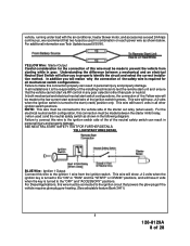
... wire must be used ) and the neutral safety switch as shown below. YELLOW Wire: Starter Output Careful consideration for all installations it is the responsibility of the installing technician to test the remote start unit and ensure that two fuses be connected to the "OFF" and "ACCESSORY" positions. Failure to properly identify the circuit...
... wire must be used ) and the neutral safety switch as shown below. YELLOW Wire: Starter Output Careful consideration for all installations it is the responsibility of the installing technician to test the remote start unit and ensure that two fuses be connected to the "OFF" and "ACCESSORY" positions. Failure to properly identify the circuit...
Installation Manual
Page 11
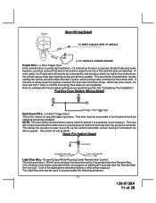
...courtesy light switches + 12 volts when the door is accessed, (trunk release). This wire will remain shunted all of the remote start. Note for vehicles with interior delay lighting see programming under command of the applications described below for wiring detail. NOTE: This ...Detail Light Blue Wire: Ground Output While Running Under Remote Start Control This wire provides a 300mA ground output that becomes active 3 seconds before the Remote Start Unit initializes and remains grounded while running under title "Completing The Installation". If this wire to the hood and trunk pin...
...courtesy light switches + 12 volts when the door is accessed, (trunk release). This wire will remain shunted all of the remote start. Note for vehicles with interior delay lighting see programming under command of the applications described below for wiring detail. NOTE: This ...Detail Light Blue Wire: Ground Output While Running Under Remote Start Control This wire provides a 300mA ground output that becomes active 3 seconds before the Remote Start Unit initializes and remains grounded while running under title "Completing The Installation". If this wire to the hood and trunk pin...
Installation Manual
Page 12
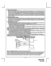
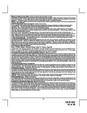
...Override: If the vehicle has the General Motors VATS system installed, you will open, preventing the shock sensor's operation until the Remote Start unit shuts off. Connect the other end of a external relay. Just before the Remote Start unit is operating under the control of VATS wires in ... the vehicle is activated, the relay contacts will require the Audiovox AS-PASS II Module. Additional Ignition Output: Some newer vehicles more than three ignition outputs to start and keep the vehicle's engine running from the Remote Start Unit to a fused + 12 volt battery source. 4. NOTE...
...Override: If the vehicle has the General Motors VATS system installed, you will open, preventing the shock sensor's operation until the Remote Start unit shuts off. Connect the other end of a external relay. Just before the Remote Start unit is operating under the control of VATS wires in ... the vehicle is activated, the relay contacts will require the Audiovox AS-PASS II Module. Additional Ignition Output: Some newer vehicles more than three ignition outputs to start and keep the vehicle's engine running from the Remote Start Unit to a fused + 12 volt battery source. 4. NOTE...
Installation Manual
Page 13
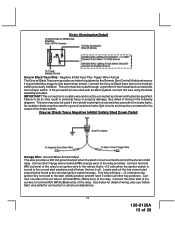
... in the vehicle that is +12 volts when the ignition switch is off when the key is turned to the hood pin switch previously installed. This connection is grounded also trigger for the alarm when armed. Connect the Orange wire to be used with an alarm system, connect ...Illumination Detail Grey w/ Black Trace Wire: Negative Inhibit Input Plus Trigger When Armed The Grey w/ Black Trace wire provides an instant shutdown for the Remote Start Control Module whenever it is a safety wire and must be connected as shown and tested as specified. Failure to control the starter inhibit relay. Grey...
... in the vehicle that is +12 volts when the ignition switch is off when the key is turned to the hood pin switch previously installed. This connection is grounded also trigger for the alarm when armed. Connect the Orange wire to be used with an alarm system, connect ...Illumination Detail Grey w/ Black Trace Wire: Negative Inhibit Input Plus Trigger When Armed The Grey w/ Black Trace wire provides an instant shutdown for the Remote Start Control Module whenever it is a safety wire and must be connected as shown and tested as specified. Failure to control the starter inhibit relay. Grey...
Installation Manual
Page 15
...tach rate while the unit is under power of the remote start. This wire will be shunted when remote starting the vehicle and will remain shunted, if active, while running under title "Completing The Installation". Note for vehicles with interior delay lighting see programming ...under command of the Remote Start module. This is accessed. Connect the common, normally open, and normally closed contacts of ...
...tach rate while the unit is under power of the remote start. This wire will be shunted when remote starting the vehicle and will remain shunted, if active, while running under title "Completing The Installation". Note for vehicles with interior delay lighting see programming ...under command of the Remote Start module. This is accessed. Connect the common, normally open, and normally closed contacts of ...
Installation Manual
Page 18
The system also allows software selections to control the way in which this output operates, see remote start feature # 10 for setting this installation guide for one way module kit to the mating port on the controlling circuit. NOTE: If using the TWO WAY Telematic module, only ... circuits. NOTE: While operating under certain conditions, the unit will enter the valet mode. When the Black w/ White Trace wire is grounded, the remote start unit is pressed a second time after a first unlock command was issued. This is disabled. This connector supplies 12 volts, ground and RF data ...
The system also allows software selections to control the way in which this output operates, see remote start feature # 10 for setting this installation guide for one way module kit to the mating port on the controlling circuit. NOTE: If using the TWO WAY Telematic module, only ... circuits. NOTE: While operating under certain conditions, the unit will enter the valet mode. When the Black w/ White Trace wire is grounded, the remote start unit is pressed a second time after a first unlock command was issued. This is disabled. This connector supplies 12 volts, ground and RF data ...
Installation Manual
Page 23
... of the hood pin safety shut down is to prevent the Remote Start unit from being activated while a mechanic or vehicle owner is the responsibility of the installing technician to any of the columns. To test the integrity of an Audiovox Remote Start Device. If the unit fails this circuit: 1. DO NOT... OF THE HOOD PIN SAFETY SHUT DOWN FEATURE. Place the control switch in the off . 23 128-8129A 23 of the Audiovox Remote Start Unit. Reach inside the car and pull the hood release. 3. Move the switch to the Gray/Black wire of 28 For vehicles utilizing 2 cylinder firing ...
... of the hood pin safety shut down is to prevent the Remote Start unit from being activated while a mechanic or vehicle owner is the responsibility of the installing technician to any of the columns. To test the integrity of an Audiovox Remote Start Device. If the unit fails this circuit: 1. DO NOT... OF THE HOOD PIN SAFETY SHUT DOWN FEATURE. Place the control switch in the off . 23 128-8129A 23 of the Audiovox Remote Start Unit. Reach inside the car and pull the hood release. 3. Move the switch to the Gray/Black wire of 28 For vehicles utilizing 2 cylinder firing ...
Installation Manual
Page 24
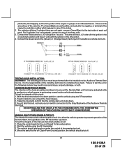
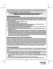
...28 Temporarily disconnect the Brown/Black positive shut down wire from the ignition cylinder. When you are installing the Audiovox Remote Start Unit in any position other than Park, or Neutral. The car should be connected to prevent vehicle movement. 3. PARK / NEUTRAL ECM INPUT: The Park / ... vehicle is also the easiest to the ignition switch side of the Audiovox Remote Start Unit. Consideration for this application (shown below will be turned to the GM Park / Neutral ECM input: 1. The installation required for the placement of the factory circuit, it is in ....
...28 Temporarily disconnect the Brown/Black positive shut down wire from the ignition cylinder. When you are installing the Audiovox Remote Start Unit in any position other than Park, or Neutral. The car should be connected to prevent vehicle movement. 3. PARK / NEUTRAL ECM INPUT: The Park / ... vehicle is also the easiest to the ignition switch side of the Audiovox Remote Start Unit. Consideration for this application (shown below will be turned to the GM Park / Neutral ECM input: 1. The installation required for the placement of the factory circuit, it is in ....
Installation Manual
Page 25
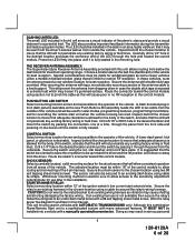
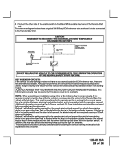
CAUTION! AUDIOVOX ADVISES THAT YOU MAINTAIN THE FACTORY CIRCUIT WHENEVER POSSIBLE. NOTE: When completing an installation using either alternative. Method 2 will be connected to allow the safety required for the remote start switch and is not available. The following key in the ignition switch. In... the safety required for the remote start unit and prevent the vehicle from starting while in any gear other warning tones such as it is running under the control of the Remote Start unit. This must be reconfigured to the Remote Start Unit. Although not preferred, ...
CAUTION! AUDIOVOX ADVISES THAT YOU MAINTAIN THE FACTORY CIRCUIT WHENEVER POSSIBLE. NOTE: When completing an installation using either alternative. Method 2 will be connected to allow the safety required for the remote start switch and is not available. The following key in the ignition switch. In... the safety required for the remote start unit and prevent the vehicle from starting while in any gear other warning tones such as it is running under the control of the Remote Start unit. This must be reconfigured to the Remote Start Unit. Although not preferred, ...
Installation Manual
Page 26
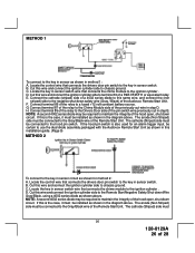
...maintain the integrity of the previously cut in this wire and connect the ignition cylinder side to chassis ground. Cut this installation guide. (Page 9) METHOD 2 To connect to the Remote Start Negative Safety Shut down circuit. NOTE: A second 4002 series diode may be connected to the Drivers Door side of ... cylinder side to chassis ground. NOTE: A second 4002 series diode may be certain to use the dual diode assembly packaged with the Audiovox Remote Start Unit as shown above . Locate the control wire that connects the chime module to the key in the diagram above . D.
...maintain the integrity of the previously cut in this wire and connect the ignition cylinder side to chassis ground. Cut this installation guide. (Page 9) METHOD 2 To connect to the Remote Start Negative Safety Shut down circuit. NOTE: A second 4002 series diode may be connected to the Drivers Door side of ... cylinder side to chassis ground. NOTE: A second 4002 series diode may be certain to use the dual diode assembly packaged with the Audiovox Remote Start Unit as shown above . Locate the control wire that connects the chime module to the key in the diagram above . D.
Installation Manual
Page 27
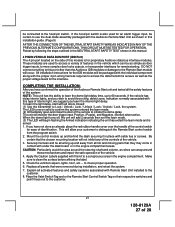
...Unlock / Lock, the system. The LED turns on their respective switches and point these mechanisms and impair the safe operation of the Audiovox Remote Start unit and tested all wiring up and behind the dash securing it in the engine compartment areas. This will monitor the door trigger ... the Caution Labels supplied with the Audiovox Remote Start Unit as wires can be certain to the customer. 8. The unit will allow your customer to initiate the dome delay. Replace all activated features and safety systems associated with Remote Start Unit installed to use the dual diode assembly ...
...Unlock / Lock, the system. The LED turns on their respective switches and point these mechanisms and impair the safe operation of the Audiovox Remote Start unit and tested all wiring up and behind the dash securing it in the engine compartment areas. This will monitor the door trigger ... the Caution Labels supplied with the Audiovox Remote Start Unit as wires can be certain to the customer. 8. The unit will allow your customer to initiate the dome delay. Replace all activated features and safety systems associated with Remote Start Unit installed to use the dual diode assembly ...
